Technically Speaking
- Author: Mike Riley, Technical Editor
- Subject Matter: Hyundai units
- Issue: Description of six-speed types
Part 2
The series of six-speed transmissions Hyundai released in 2009 has three basic levels or sizes that can overlap vehicle models and engine displacements. As a result, technicians must verify the specific model before ordering any replacement components.
The units, designed to accommodate a wide range of Hyundai and Kia applications, are not a Mechatronic design (internal TCM), but there is still a lot to contend with. This concluding segment completes a description of transmission functions.
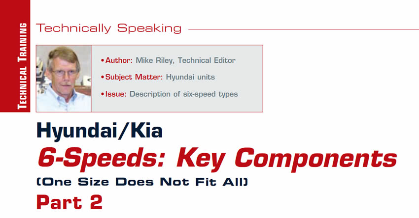
OWC/Inner Race
Depending on manufacturer, a six speed automatic may or may not contain an OWC (one way clutch). The Hyundai A6 models just happened to have one, which is a rather large diameter roller clutch (Figure 1). The outer cam is held in place with snap rings, and to ensure that it is installed correctly the word “FRONT” is stamped into the surface of the cam. The inner race serves more than one purpose due to design. There are two different clutch hubs that are part of the assembly, the L-R brake and the overdrive clutch positions. The inner race and thus the input carrier can be held stationary by either the low roller clutch or L-R brake, or driven by the OD clutch assembly.
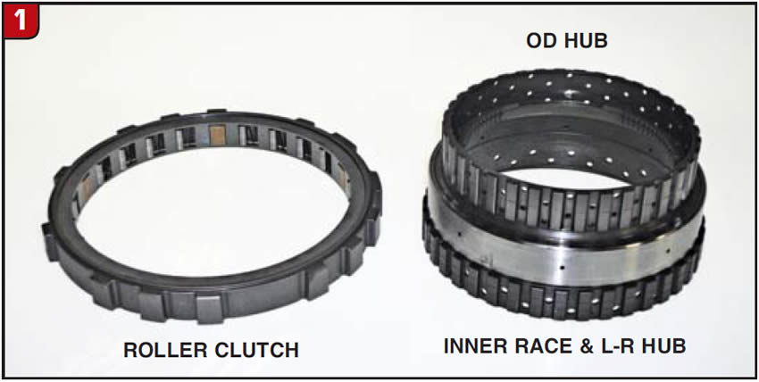
Low-Reverse Brake Assembly
The third and final stationary clutch in the transmission is the L-R brake, which is located in the back side of the main case. The L-R brake piston fits into the case bore and has a large coil type return spring (Figure 2). The clutch pack is fairly straightforward, in that there is an apply plate, frictions/steels and a backing plate, which is positioned next to the OWC. There is also a cushion plate that goes next to the piston. The L-R brake and UD brake apply holes are located in the center of the case under the valve body.
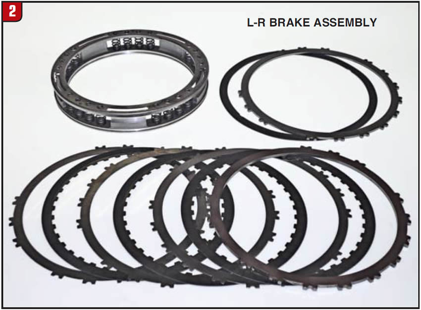

Overdrive Clutch Assembly
The other rotating clutch in the transmission is the overdrive clutch assembly. The OD clutch drum is somewhat unique, due to having not only splines for the input shaft, but a rear sun gear as well. The sun gear meshes with the backside of the input planetary and is the starting point of the power flow (Figure 3). As with the 3-5/R clutch, the OD apply piston is steel and there is a bonded retainer (balance piston), but the return spring is a coil-type spring. The frictions are double-sided and segmented, and the clutch pack uses a regular backing plate.
End Cover
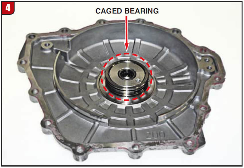
The transmission end cover is a fairly standard aluminum cover, found on many other FWD applications. There is a caged bearing in the cover to support the tip of the input shaft, and fortunately the sealing ring tower is steel, not aluminum, which should limit ring groove wear (Figure 4). RTV is used to seal between the end cover and case and the transmission type is cast onto the outside of the cover for identification purposes.
Differential/Transfer Gear
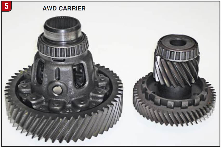
The transfer/pinion gear assembly is supported by tapered roller bearings and the park gear is also part of the assembly. The differential carrier, two-wheel drive or four-wheel drive, is fairly robust due to having four pinion gears instead of two (Figure 5). Depending on model, the carrier will have metal clad seals and O-rings that must be changed to avoid leaks. The differential also uses tapered roller bearings. If any of the main components are changed, a bearing preload procedure must be performed.
Valve Body/Solenoids
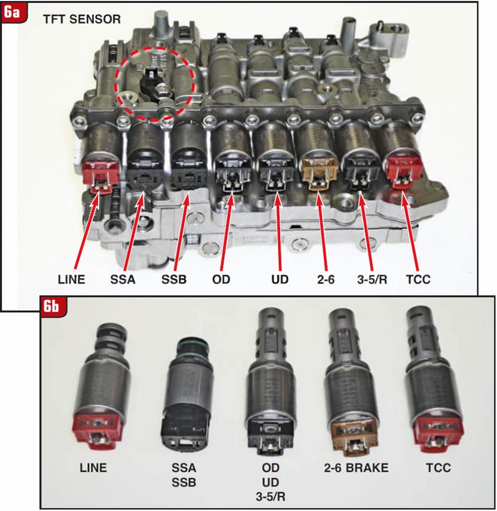
Even without Mechatronics, the valve body assembly could be a chore to deal with. There are several accumulator pistons, a slew of valves and springs, as well as other assorted do-dads such as clips, check balls and thimble screens. In addition, there are eight “count ’em” solenoids, all of which must be tested (Figure 6A). There are five basic types of solenoids, based upon design, operation or part number. Two of the solenoids are simple on-off while the other six are PWM designs. The two on-off solenoids (SSA, SSB) are normally closed (NL = normally low). Of the PWM solenoids, there are two that are normally low (TCC, 2-6) and four that are normally high (open) which are the OD, UD, 3-5/R and line pressure. The line pressure solenoid is a different part number from the other three and has a red cap, instead of black. The solenoid styles are illustrated in Figure 6B. The two on-off solenoids have a resistance of approximately 10 ohms, whereas the PWM solenoids have approximately 5 ohms. The valve body also contains a TFT sensor.
Electrical Components
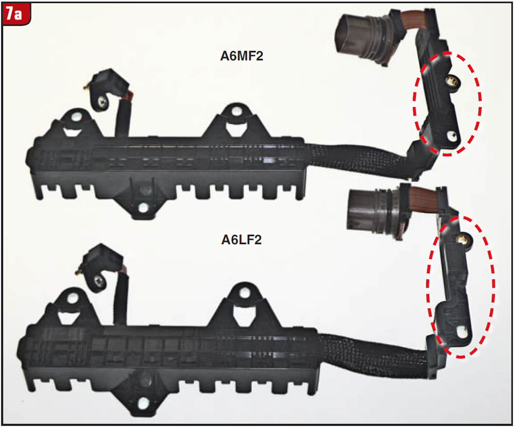
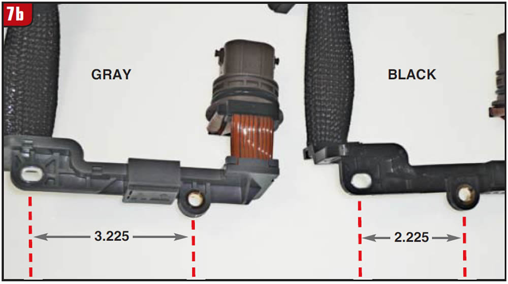
The electrical case connector utilizes a wire ribbon to connect to the solenoid collector plate and input/output speed sensors. The assembly is dependent upon application due to case size variations between the A6L, A6M and A6G units (Figure 7A). The hold down bracket bolt hole spacing will vary as does the color of the bracket. For instance, the A6L is gray with a wide spacing and the A6M is black with the narrow bolt hole spacing. Measure the bolt hole spacing to obtain the proper part (Figure 7B).
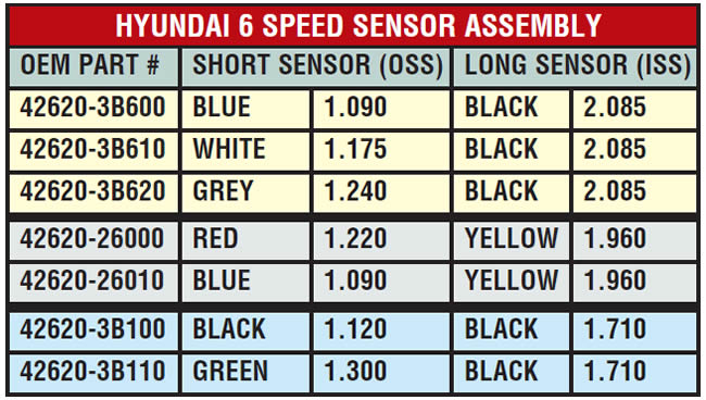
The input/output speed sensor assembly is where things really get wild. To date, there are seven different part numbers available to fit a variety of applications. Both sensors push through holes in the case to register against the rotating components. The long sensor is the ISS and reads signal from the OD clutch drum, whereas the short sensor is the OSS that picks up the signal from the output gear. The drum and gear diameters dictate as to which sensor assembly is needed to obtain the proper air gap, which should be around a 0.030” gap. Fortunately, the sensors are color-coded (Figure 8).
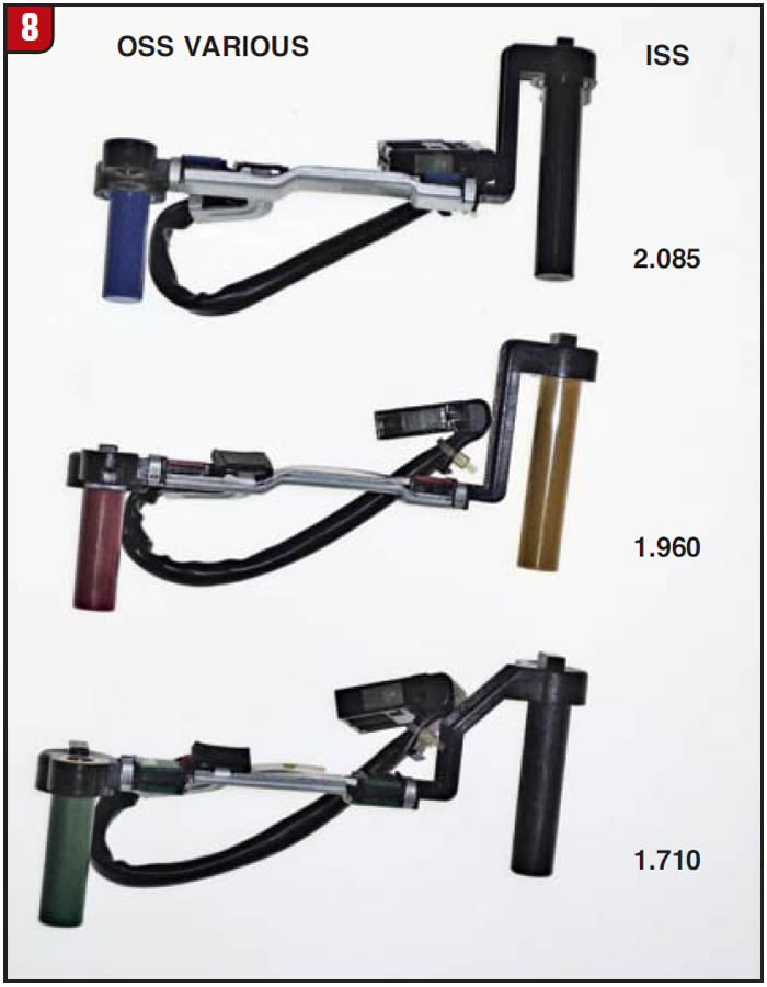
The enclosed chart gives the color and dimension information along with the OEM part numbers.
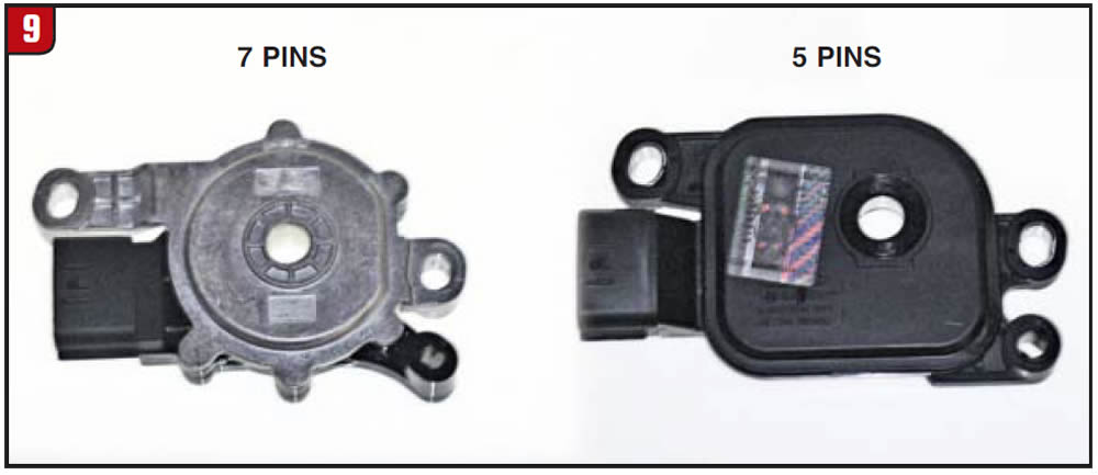
The last electrical component to be concerned with is the MLPS (inhibitor switch) and for the same reason, dimensions, etc. Again, the case size will dictate as to which inhibitor switch is needed. The hold down bolt/connector style needs to be checked to obtain the correct part (Figure 9). For instance, the silver top switch has seven pins and the black top has five pins. There is a tab on the switch that is used for adjustment by placing the shifter in neutral and aligning the switch holes. A major plus for the A6 units is that there is a pressure test plug for every element used in the transmission.
With the amount of Hyundai and Kia vehicles on the road today, it’s just a matter of time before one rolls into the shop for repair. Despite the model, make sure of the transmission that’s in it before doing diagnosis, repair or replacement and not just base it on engine size or the wrong widget may show up.


