Technically Speaking
- Author: Mike Riley, Technical Editor
- Subject Matter: Hyundai units
- Issue: Description of six-speed types
Part 1
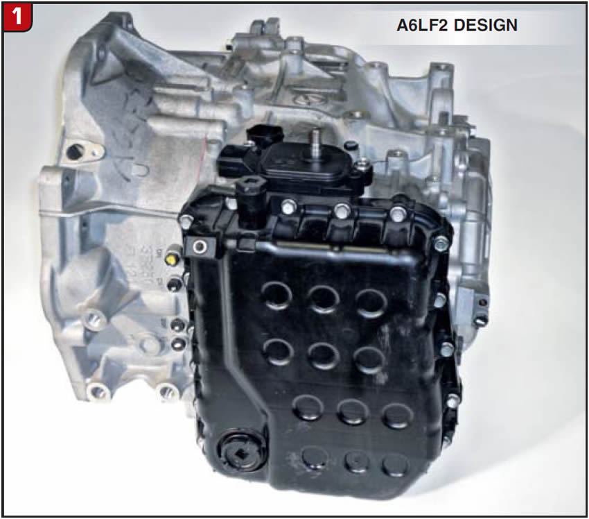
Although Hyundai was not the first manufacturer to offer a six-speed automatic transmission, they ultimately made up for lost time. In 2009 the car company released a series of six-speed transmissions to accommodate a wide range of Hyundai and Kia applications. The transmissions can be FWD or AWD and are rather compact in design (Figure 1). There are three basic levels or sizes that can overlap vehicle models and engine displacements.
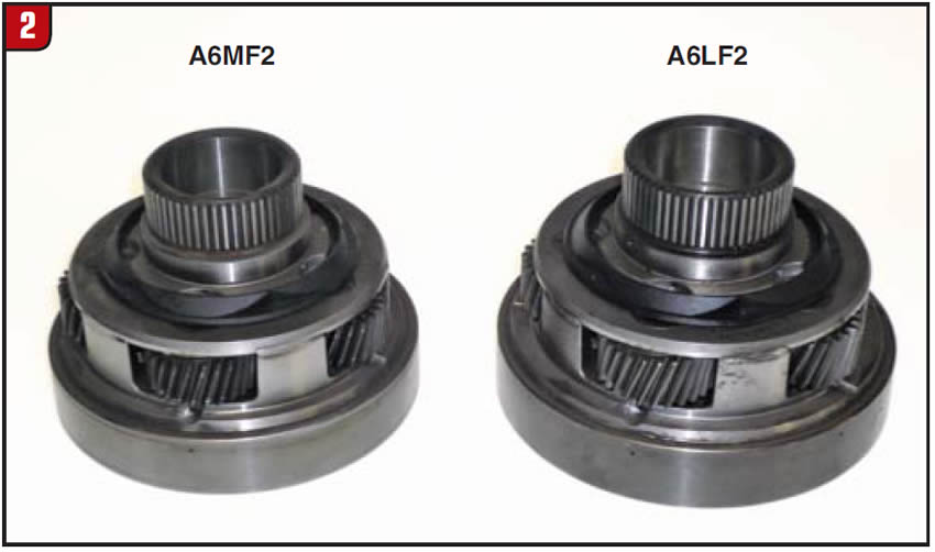
The base designation for a given transmission platform is A6LF—(large), A6MF— (medium), and A6GF—(small), along with a subset number 1/2/3 to denote capacity, etc. There is also a hybrid version available for certain applications, which is model number A6MF2H. The hybrid operates similar to Honda applications with IMA (integrated motor assist) and uses an electric motor and start clutch. Most of the transmission however, is similar to the regular A6M unit. As in the case of the Mitsubishi F4A41/F4A51 transmission models, the Hyundai A6 units are all about size (Figure 2). To illustrate the difference between models, Figure 2 contains the output planetary from the A6M and A6L transmissions. Most components share that distinction. Although the transmissions are not a Mechatronic design (internal TCM), there is still a lot to contend with. Due to inconsistencies and overlap, verify the transmission model for a given vehicle before ordering any replacement components.
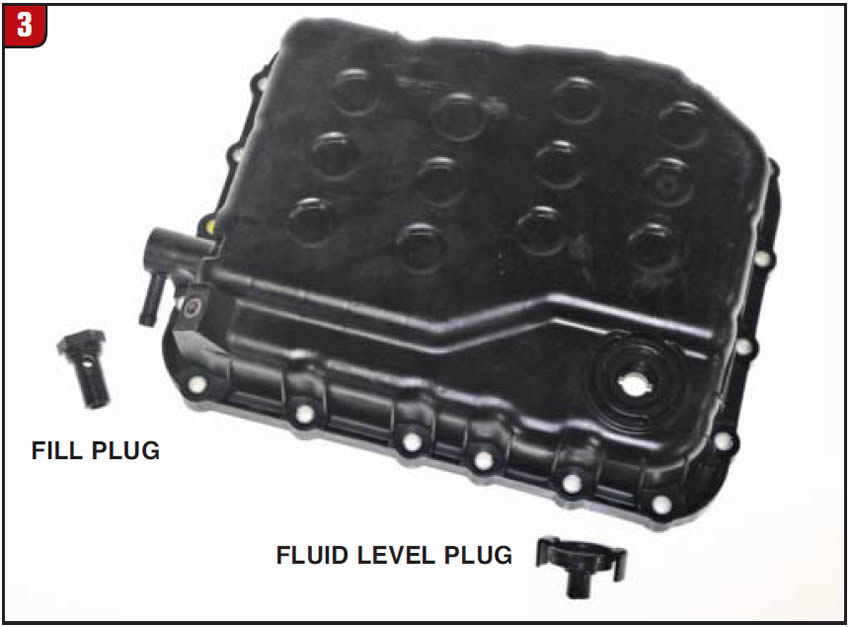
Valve Body Side Cover
As with most FWD six-speed transmissions, the Hyundai units have no bottom pan, but rather a valve body side cover (Figure 3). Depending on model, the side cover could be metal or plastic, which would also affect gasket material and design. The transmission-fluid drain plug is located at the bottom of the transmission case, whereas the cover contains the fill plug as well as a fluid level plug. With the engine running and the transmission fluid at the correct temperature, merely raise the vehicle and remove the fluid level plug to see if a little fluid will run out. If needed, remove the fill plug at the top, which doubles as the transmission vent, and add fluid until it starts to trickle out of the fluid level hole.

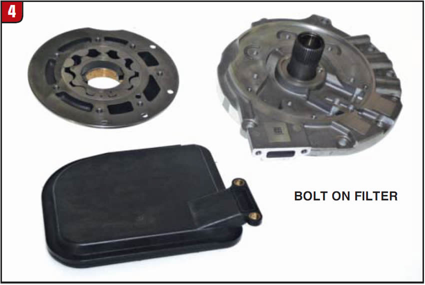
Pump/Filter Assembly
The pump assembly is a squished design, meaning that it is fairly flat. The pump actually bolts to the transmission case and there is no bellhousing to pump body bolts. The cast iron pump body has a simple O-ring that contacts the bore of the bellhousing for sealing. The stator support is relatively short (Figure 4). Unlike other models, the transmission’s sump filter bolts to the aluminum pump cover, but beyond that it is a simple G-rotor design.
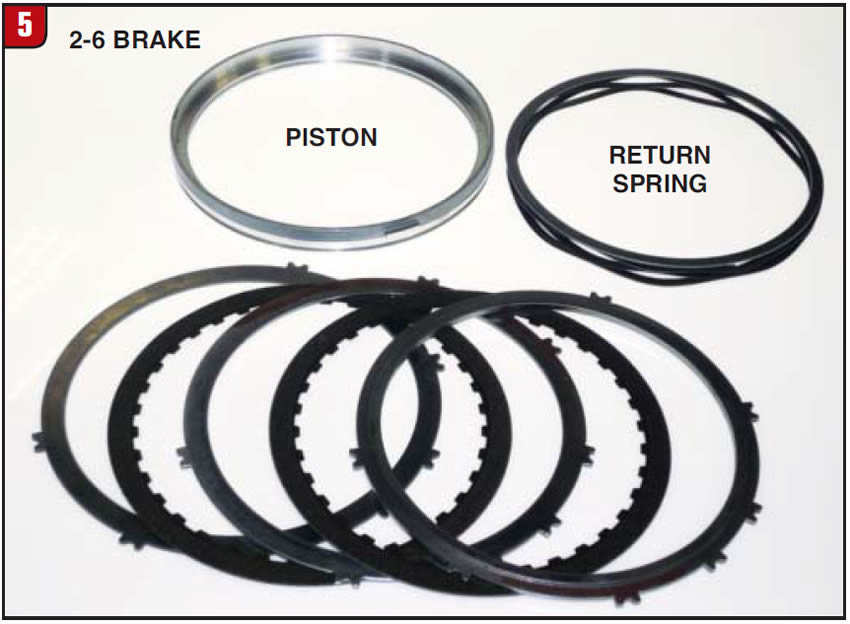
2-6 Brake Assembly
The first friction element at the front of the transmission is the 2-6 brake (Figure 5). The cavity for the apply piston is in the back of the pump cover. The 2-6 brake apply piston is a thin wall piston similar to the VW 09G B1 piston and return the spring is an accordion type. There is also a spacer plate that goes between the spring and the first steel. The steels spline to the main case and the backing plate goes against the UD brake assembly. Use a proper procedure to obtain the correct clutch clearance.
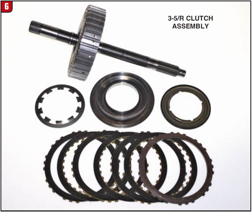
3-5/R clutch Assembly
The front rotating clutch in the transmission is the 3-5/R clutch, which is located directly behind the pump. At first glance, the housing resembles the forward clutch on the Ford FNR5 transmission, but has a different purpose (Figure 6). The input shaft is made to the clutch housing and utilizes a steel piston with a Belleville return spring. In addition, there is a bonded retainer to use for balance oil and the frictions are single sided. Always ensure that the input shaft sealing ring grooves are not worn.
Clutch Hubs
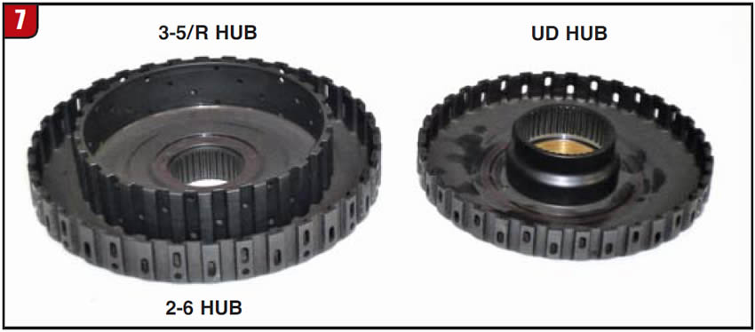
The next items in the transmission that stack up behind the 3-5/R clutch assembly are clutch hubs, three to be exact. The front hub is actually a dual hub assembly, which splines to not only the 3-5/R rotating clutch but also the outer portion splines to the 2-6 brake assembly (Figure 7). Right next to the dual hub is the hub for the UD brake assembly. The UD hub bushing rides on the journal of the dual hub, and there is a thrust washer that separates both components.
Underdrive Brake Assembly
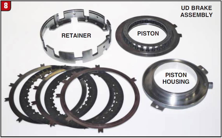
The third friction element within the transmission is the UD brake assembly. The UD brake is a rather unique design that consists of a steel retainer, aluminum piston housing, steel apply piston, coil return spring set and frictions/steels, (Figure 8). The retainer bolts to the case through the output gear support and butts up against the 2-6 brake assembly. The piston housing appears to just float inside of the retainer but is actually held in place by two bolts. The friction plates are the segmented design. As with the 2-6 brake, use the correct clutch clearance procedure.
Output Gear/Support
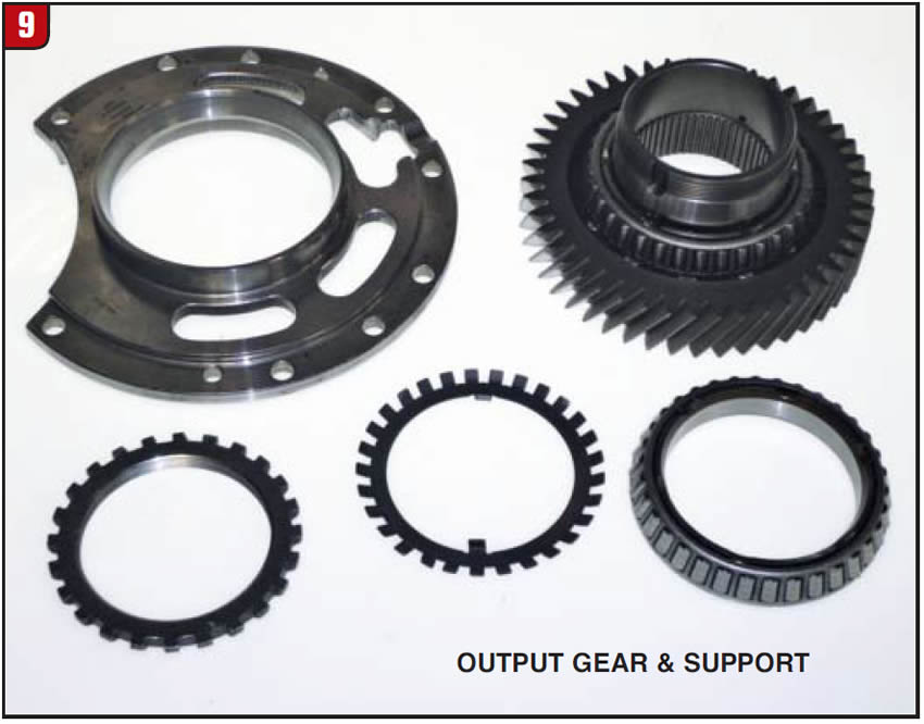
Unlike other transmission designs, the output gear and support are relatively easy to remove. Once the UD brake assembly is out of the way, the out-put gear and support will lift upward and out of the case. The output gear is supported by two large tapered roller bearings and is held to the support by a serrated nut and lock washer (Figure 9). The output gear is splined directly to the output planetary. As with any other component that uses tapered roller bearings, proper preload is required, therefore having the correct spanner socket and torque information is a necessity. The ratio
(diameter) of the output gear will dictate as to which output speed sensor is needed to provide the correct air gap.
Output Planetary
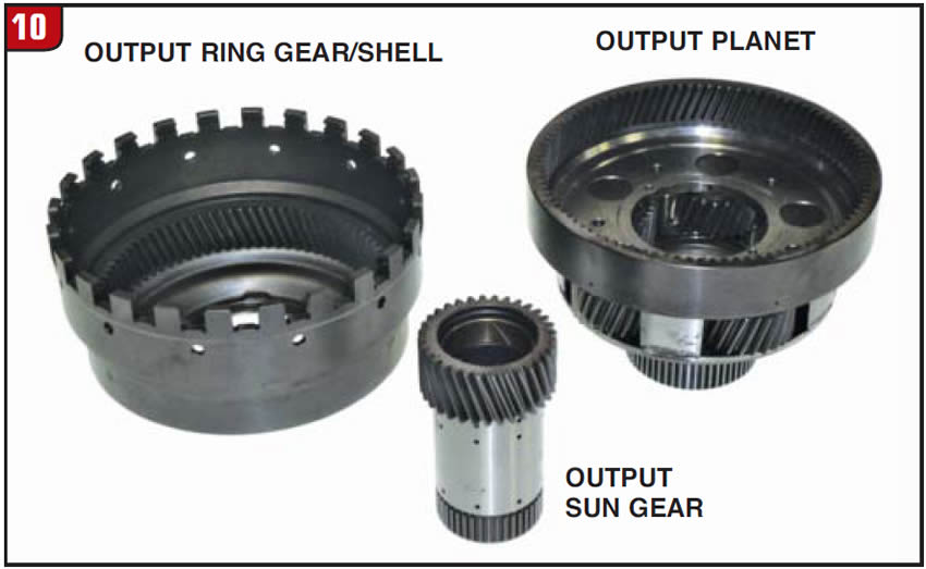
The planetary system that is utilized by Hyundai is also somewhat backwards from other transmission types relating to position and function, although overall clutch operation does mimic the GM 6T70. The planet set closest to the front end of the transmission is the output planet. The output planetary is a simple planet design, with one sun gear, ring gear and one set of planet pinions (Figure 10). As stated, the output planet splines to and drives the output gear and also has the No. 2 ring gear made to the carrier. The output (large) sun gear extends through the output carrier and can be held stationary by the UD brake. The output ring gear is part of the shell that also meshes with the No. 3 ring gear.
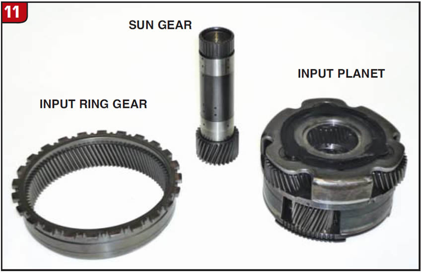
Input Planetary
The rear (input) planetary carrier may appear to be a compound planet design; however, it isn’t. The carrier is basically two simple planetaries welded together, each having a different diameter (Figure 11). The forward (small) sun gear goes into the front side of the input planet and extends through the large sun gear to mesh with the 3-5/R clutch hub. Depending on gear ratio, the small sun gear will either be driven by the 3-5/R clutch or held stationary by the 2-6 brake. The ring gear shown in Figure 11 is for the smaller diameter pinion set, which is the rear set and the drive lugs connect with the output ring gear shell. The input planet carrier also meshes with the OWC inner race and both planets have plastic oil dams.