Leeward Tech
- Author: Ed Lee
- Subject Matter: Rebuilt converters
- Issue: The effects of changes
When you cut open a rebuilt converter, you never know what you will find. There are always similarities in the converters because most rebuilders follow the same basic format. It is the differences in the rebuilt converters that make them stand out. Some of the differences come from not knowing what you are doing. A few of the rebuilders still use the same welder back-off for the converters where the turbine hubs touch the cover as well as the converters that the turbine hubs that do not touch the cover.
You can always recognize a converter built by one of these rebuilders because the end play will not be correct for either type of converter. The converter where the turbine hub touches the cover will have too much end play. The converter where the turbine hub does not touch the cover will not have enough end play. Even when a converter is built correctly there may be some “improvements” or other subtleties that personalize that converter to its rebuilder. Some questions arise as to whether these “improvements” or differences actually help or hurt the converter.
Bending Vanes
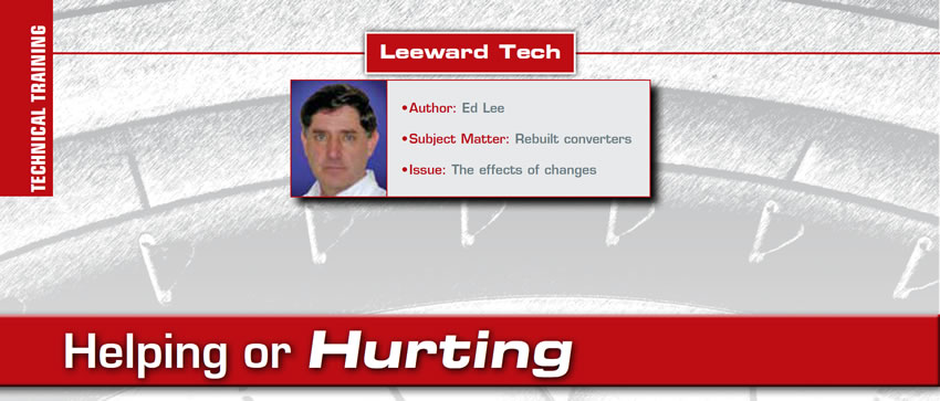
Bending or tweaking the exit angle of the impeller vanes is a widely used practice across the converter industry. It is a good method of making minor adjustments to the “stall” of a converter. A small adjustment toward the high or low side of the exit angle of the impeller vane will raise or lower the stall about 100 rpm.
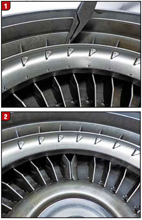
There are also some instances where bending the vanes is not very helpful. The bent vanes in Figure 2 were found in a converter that was sold as a “high-stall” converter. The bent vanes were in (4) equally spaced places around the impeller. The converter did have a higher stall as advertised, but the customer also expected some level of enhanced performance. In reality you could almost walk as fast as the vehicle would accelerate with this modification.

Machined Stators
The greater the distance between the stator and the impeller, the lower the stall of the converter will be. The “Mileage Master” converter was created during the fuel crisis by adding a shim under the impeller side stator bearing. The shim moved the stator away from the impeller lowering the stall and improving fuel economy. Machining the impeller side of the stator will have the same results. You can convert the stall and “K” factor of a high stall stator to a medium stall by machining .125” off of the vanes on the impeller side of the stator. This same modification can be a performance enhancement when used with a Cummins diesel power plant. The inline configuration and long stroke of the Cummins engine works well with the lower stall. Unfortunately, this modification is application specific. If you use it with any of the diesel power plants with the V-8 configuration you will create an off idle hesitation or turbo lag.
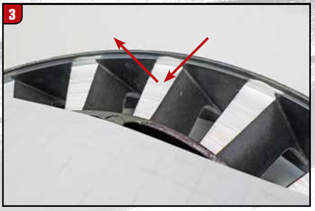
On the other side of the stator, the turbine side, the distance to stall relationship works in reverse: the greater the distance between the stator and turbine the higher the stall. Machining the vanes on the turbine side of the stator will also raise the stall. This is NOT a good way to raise stall because a portion of the oil that travels from the turbine to the stator will strike the flat area created by the machine process and deflect it back into the turbine.
The deflected oil will slow the rotation of the turbine negating any gains from the higher stall.
Another machine process on the stator is used to open up the windows on the stator. This process allows a larger volume of oil to pass through the stator.
This modification works well on the Cummins diesel converters.
Rolling the Inner Edge of the Torus Rings
There is one torus ring in the impeller and one in the turbine. The oil flows around the torus rings as it passes through the vanes of the impeller and then through the vanes of the turbine.
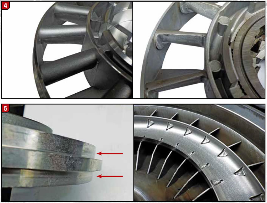
The torus rings help to direct the oil as it enters and exits the stator. The inner edge of the torus rings fit into the upper and lower steps located at the O.D. of the stator. The torus rings keep the oil from spilling passed the O.D. of the stator making it more efficient. This proximity of the torus rings to the stator can also be a noise source if everything is not running true. Some shops bend the inner edge of the torus rings away from the stator for extra clearance. This generally does not cause any noticeable issues. However, with a performance converter that is not spragless this should not be done.
The interaction of the oil between the stator and torus ring help to start the stator to free wheel. Think about it as being like the waved washer between the TCC piston and turbine on the early GM Lockups. The waved washer would start the TCC piston moving forward like the oil starts the stator to move. The freewheeling stator translates to “mile per hour” in a racing converter.
So regardless of your opinion about the changes that have been made to a converter, you can probably get some good arguments from either side as to whether the changes to a converter help or hurt the converter.


