Tech to Tech
- Subject: Diagnosing a no-start condition
- Vehicle Application: 1993 Pontiac Grand Am
- Essential Reading: Diagnostician
- Author: Jeff Bach
Fixing ’93 Pontiac Grand Am no-start like old bad dream
When I was a kid, I used to have this recurring bad dream that I was running from something and getting away, then I would get to the corner of our yard and I’d go into slow motion. It was like trying to run through Jell-O or something. I’d struggle with all my might and get to the porch, then I’d wake up panting in a cold sweat.
I haven’t thought about that dream for a long time. Then I found myself working on this ’93 Pontiac Grand Am no-start. It’s a 3.3-liter V-6. It has the characteristic look of a car that has been saved for slow times, judging from the rusty belt (Figure 1).
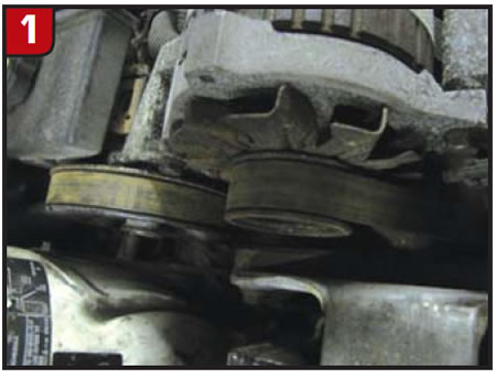
This belt has rust on the back of it due to cranking an engine with rusty pulleys. This is a sight reserved for those of us who get to work on cars that have sat for extended periods of time (except in Arizona). The rust won’t last very long once the engine starts.
The guy who sent it here has a shop, and we don’t see many cars from him. I fully expect that the problem he has run into with this car has him at his wit’s end.
Whenever I start on a car such as this, I try not to make too many judgments. I find that it works better for me to do the basic testing while pretending it is just a normal “no-start.” After doing a few quick checks, we determined that the car was not getting a reference signal on the purple-with-a-white wire. My favorite quick check for making this determination is the fuel-pump-relay test. By putting a test light in the fuel-pump circuit at the relay and cranking the engine for several seconds, you can watch the light go out after two seconds of cranking.
If you were out on the road or in a parking lot with no tools, you could get this information by feeling the relay while someone cranks the engine. This tells me that the engine control module (ECM) is letting go of the fuel-pump-relay drive circuit because it is not getting an rpm reference signal from the module. The module gets the signal from the dual crank sensor.
I now have a direction to go with my testing. I took a volt/ohmmeter and tested the four wires from the module to the crank sensor. All four circuits were showing voltages, none below 5 volts. One of these wires is supposed to be a ground. While drop-testing the groundside voltage, I got the reading in Figure 2.
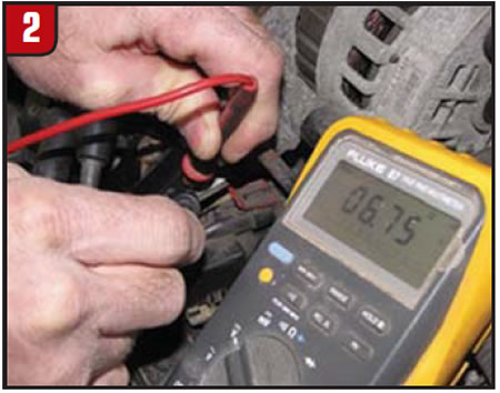
Note the position of the volt/ohmmeter leads. There was more than a six-volt drop between the module base and the engine plate that it bolts to. I can see where this could cause some confusion. I was told that this car had had several crank sensors, another ECM and another ignition module put on it.
I pulled the module off the engine mounting plate and could see where it had been recently cleaned, along with the bracket to which it was fastened. A little further investigating revealed that the aluminum plate on the bottom of the module actually comes off. This plate looks as though it’s actually part of the module and is sandwiched between the module and the engine bracket. There was a definite layer of oxidation built up between the plate and the module. I cleaned this plate and the module, applied heat-transfer compound and reassembled the thing. Still no fuel-pump-relay action after two seconds of cranking.
Retesting the four wires from the module to the dual crank sensor, I now had a ground, a 12-volt wire and two varying signal circuits. Next, I grabbed my scope and took a look at the reference circuit and the 18X crankshaft-position (CKP) signal shown in Figure 3.
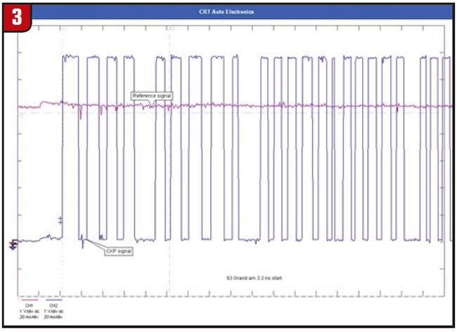
The 18X looked a bit odd with the suspicious gap at odd intervals. I have to say this was the first time I had encountered this signal and wasn’t quite sure what to make of it. The other interesting thing was that there was still no reference signal. Next, I tested the 18X signal against the 3X and got the screen shown in Figure 4.
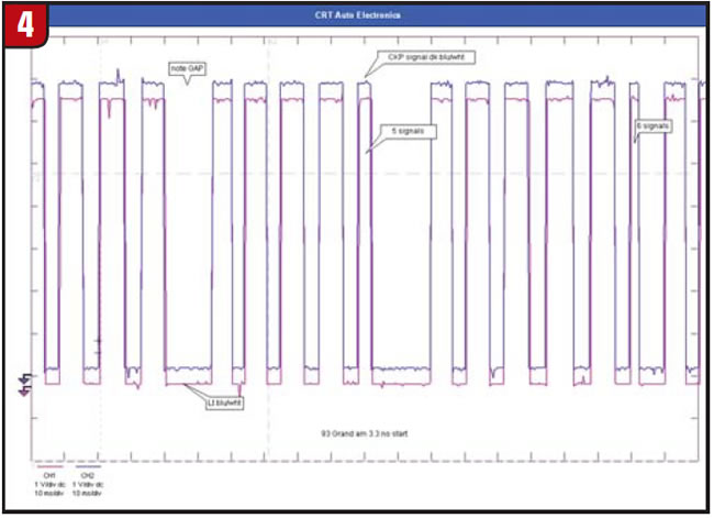
Now there was another one for the book. These two signals should not look the same. It looked as though both CKP signals were tied together. We disconnected the sensor harness and tested each circuit for continuity and shorts. All the circuits were good between the sensor and the module. This left us thinking the problem had to be an internal short in the CKP sensor.
Realizing now how easy it can be to get twisted up on a car like this when you’re relegated to normal tests by the book, testing with a few known good parts and trying even a few new ones, I realize the importance of even a simple dual-channel oscilloscope. It has become one of the biggest reasons why we’re doing work when other shops around here are completely dead this time of year, especially in this economy.
I could see this causing some head scratching. The signals shown in Figure 4 left us no alternative but to get another CKP sensor. This would be about No. 4 or No. 5, I’m guessing from the information I was given. The only thing that makes sense about this scenario now is that with the module not being grounded, the primary current back-feeding through the sensitive Hall-effect sensors in the CKP – well, you do the math.
I’m careful to order the new sensor from a supplier that hasn’t been sourced for this car. I can believe the stories I hear occasionally that start out, “It took three new sensors before we finally got a good one.”
Once we got the new sensor installed, I cranked the engine and saved the waveforms in Figure 5.
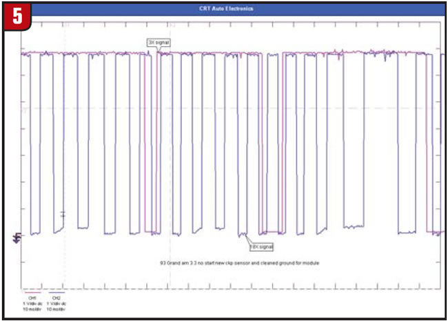
Amidst a cloud of loose rust and debris from a mud-dauber nest attached to the power-steering-pump pulley, the engine chugs into life again. It takes a minute or two for it to clear (I’m guessing from various incendiary liquids sprayed into the air intake). The engine finally smoothes out and runs as if it has been doing so all along. I checked all the fluids, added some antifreeze, then headed out into the 15°F snowy wind. The roads are still covered from the dumping we got this week. The rotors have the familiar rust noise that comes from sitting more than a few weeks here in the Midwest winter season. After about five miles of road test, I’m satisfied enough to call my customer and give him the welcome news that this thorn has been pulled.

Jeff Bach is the owner of CRT Auto Electronics, an ASA-member shop in Batavia, Ohio. For more information on this topic, contact Bach at 515-732-3965. His e-mail address is [email protected] and his Web site is www.currentprobe.com.
This copyrighted article is reprinted with the permission of AutoInc., the official publication of the Automotive Service Association (ASA). To learn more about ASA and its commitment to independent automotive-service and repair professionals, visit www.asashop.org or call 800-272-7467.