Technically Speaking
- Subject: Valve-body and solenoid operation
- Unit: GM 2MT70
- Vehicle Application: 2009 Saturn Vue 2.4-liter
- Essential Reading: Rebuilder, Diagnostician
- Author: Wayne Colonna, ATSG, Transmission Digest Technical Editor
Part 3
Getting into the valve body is all we need to do to finalize our brief look at GM’s front-wheel-drive two-mode hybrid transmission.
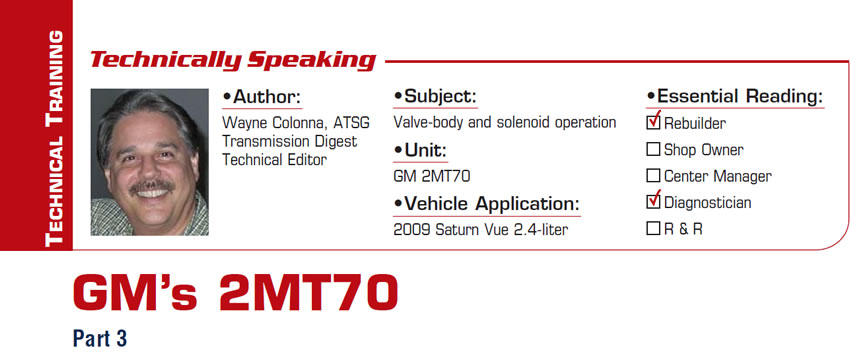
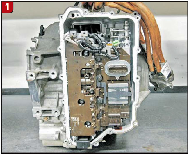
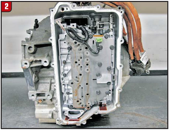
If you recall from the first article, the TCM and solenoid-body assembly is first removed from the transmission followed by the plate attaching the assembly to the valve body (figures 1, 2 and 3).
However, once the valve body is removed (Figure 4) you will notice three orifices pressed into the casting.
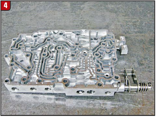
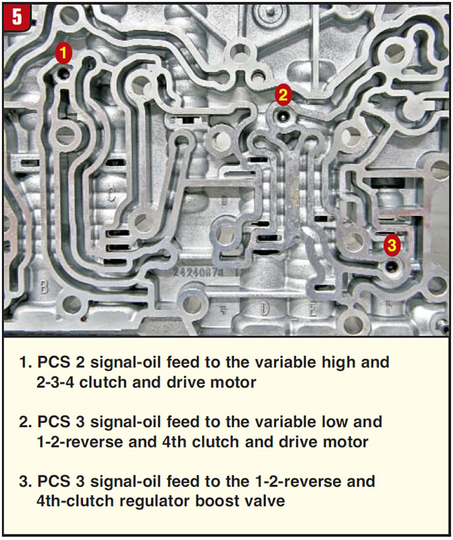
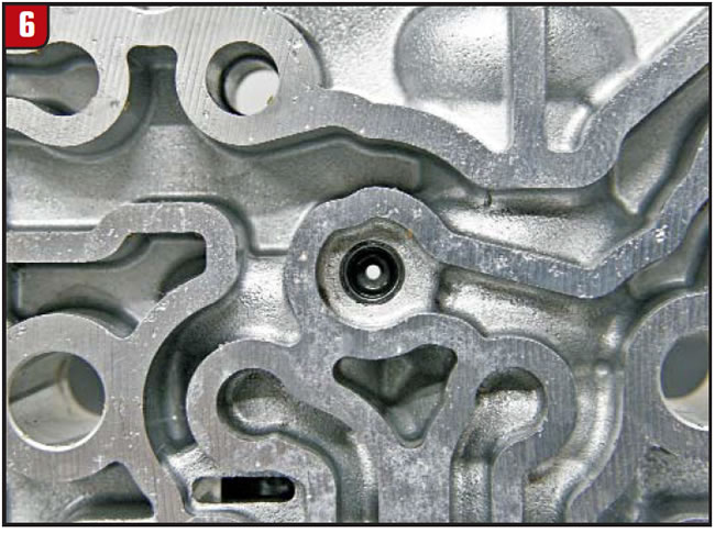
Each of these orifices is about 0.045 inch, and two of them are for pressure-control solenoid 3 signal oil; the remaining one is for pressure-control solenoid 2 signal oil (figures 5 and 6). These make for good trash collectors, causing additional problems to the operation of the transmission.
After all, the question you have to ask yourself is, “Where is the trash clogging these orifices coming from?”
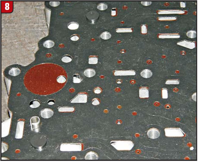
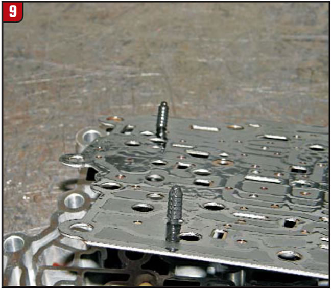
The case side of the valve body has a bonded spacer plate that is bolted down on one end and two plastic retainer pins at the opposite end (figures 7, 8 and 9). Once this plate is removed, there is only one white 0.250-inch plastic checkball to watch for.
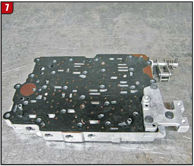
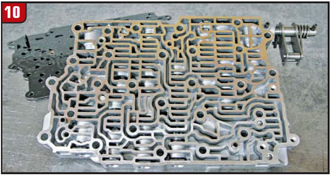
Many times it sticks to the plate and can fall away unnoticed (figures 10 and 11). The function of this ball seems to be similar to that of the numbers 1 and 2 balls in the rear-wheel-drive version of this transmission (Transmission Digest, April 2010).
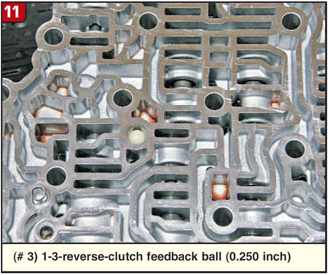
The exception here is that actuator-feed-limit (AFL) pressure is routed to this # 3 checkball, pushing it onto its seat. According to OE hydraulics, 1-3 reverse-clutch feedback pressure works on the opposite side of this ball in 1st and 3rd gears only. Even though the AFL valve is known for wearing its bore, causing a loss of solenoid feed pressure, it appears that in 1st and 3rd gears this 1-3 reverse-clutch feedback pressure will push the # 3 ball in the opposite direction of the opposing AFL pressure supplying pressure in the AFL circuit.
But the way that the ball pocket is designed, slots alongside the ball will allow this 1-3 reverse clutch feedback pressure to get around the ball and feed the AFL circuit even if AFL pressure has not been compromised by a worn AFL valve bore. Regardless, the AFL valve is the number 4 (L) valve in Figure 12 and should be on your list of bores to check for wear.
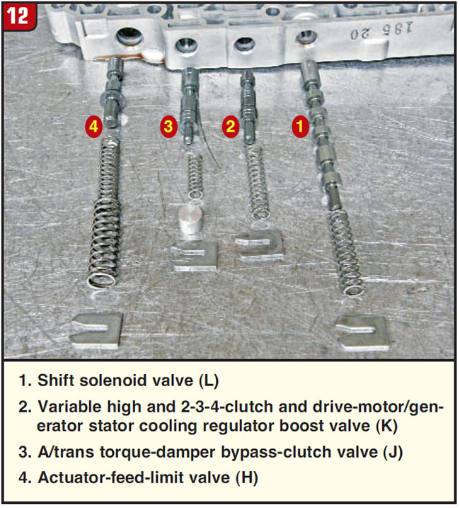
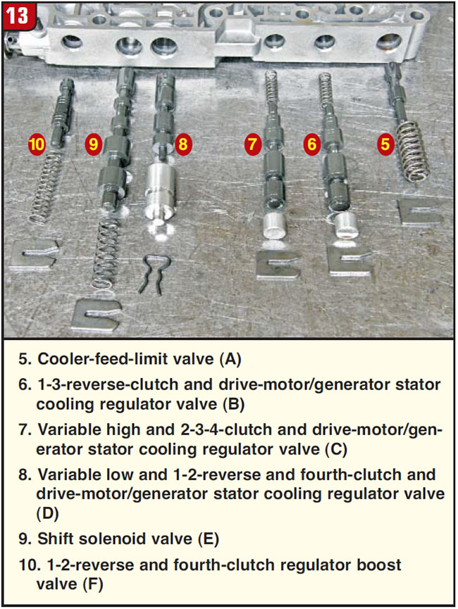
Figures 12 and 13 identify all the valves in the valve body. You may have noticed letters cast into the valve-body above each of the valve bores in Figure 5. The legends for figures 12 and 13 that provide the names for these valves also provide the letter for each bore cast into the valve body.
From looking at some of the names of the valves in this transmission, it seems much easier to refer to them by their letters rather than by their name. Some of the valve names are so long, you might as well call one of them supercalifragilisticexpialidocious!
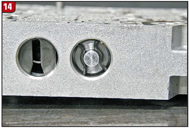
This makes talking about the No. 8 valve (D) in Figure 13 so much easier. This is the only valve lineup that uses a hairpin-style clip (Figure 14). This valve lineup routes oil to the 1-2 reverse clutch in 1st, 2nd and Reverse and to the fourth clutch in fourth.
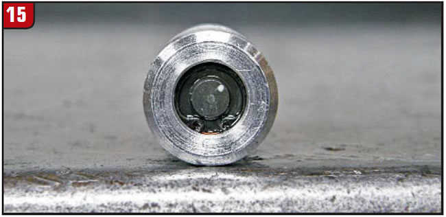
It has a spring-loaded valve held into a sleeve with the smallest C clip I have ever seen in a transmission (figures 15 and 16).
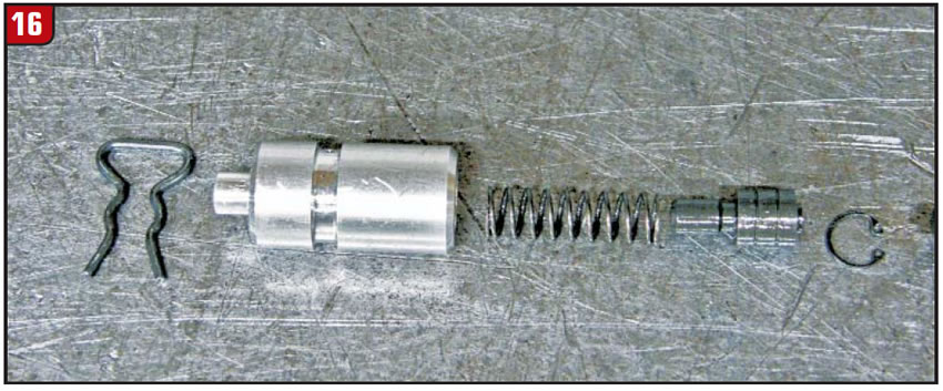
The clutch-application control from this valve is delicately achieved by PCS 3 at one end of the valve lineup and 1-2-Reverse/fourth-clutch boost-valve pressure (from valve 10 [F] in Figure 13) at the opposite end through an orifice of about 0.050 inch in the sleeve (Figure 17).
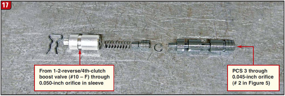
You can imagine the symptoms the transmission would experience should the 0.050-inch orifice in the sleeve become restricted with debris as with the 0.045-inch orifice for PCS 3 signal oil at the opposite end of the lineup.
The small valve in the sleeve also may become stuck with slight debris. In fact, the valve in this transmission that Alto provided was stuck because of small debris, which is what caught my attention and prompted me to mention it to you here.
This concludes the brief overview series of GM’s two-mode hybrid transmissions, both rear- and front-drive applications, keeping you aware of what may enter your shop any day now.


