
Up to Standards
- Subject: Identification, theory of operation, repairs
- Units: MP 1222, 1225, 1226, 1625, 1626, 3023, 3024
- Essential Reading: Rebuilder, Diagnostician, R & R
- Author: Mike Weinberg, Rockland Standard Gear, Contributing Editor
New Venture Gear, a manufacturing arm of Chrysler Corp., was bought some years ago by Magna International, a supplier of parts to automakers around the world. The division that produces the transfer cases has been renamed Magna Powertrain. GM introduced a new series of transfer cases in mid-2007, and these units are now coming into our shops for work. This will be the first in a series of articles regarding these transfer cases and going over identification, theory of operation, and overcoming some design defects and issues that are now showing up in the marketplace.
Each model of transfer case built by Magna Powertrain has MP (Magna Powertrain) before the model number. There are nine models of this design, and they are identified by GM according to RPO codes for the vehicle. An ID chart is included here to help identify the units.
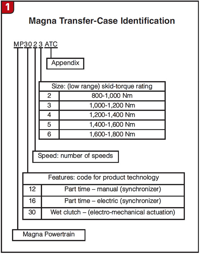
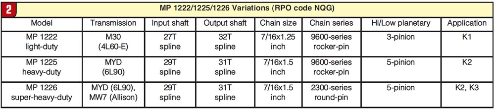
They range from light-duty to heavy-duty, depending on the torque rating of the power plant in the truck, and can be broken down into three subgroups: manual shift – RPO Code NQG, which includes models MP 1222, MP 1225 and MP 1226; electrically shifted models, RPO code NQF, models MP 1625 and MP 1626; and active transfer case (computer controlled with internal wet-clutch packs) – RPO code NQH, models MP 3023 and MP 3024. These units collectively replace the NVG 246, 261 and 263 models we have been working on for years.
The manually shifted models are self-explanatory, with the driver having complete control over engagement and operation of the transfer case through a manual shift lever. The electrically shifted units (RPO code NQF) are driver controlled by an electronic switch and motor on the transfer case to engage the modes and ranges available without having to move a lever manually. There is little difference between the manually and electrically shifted models except for how they are shifted.
We now come to the active or computer-controlled models, which involve electronic shifting by the driver for range and mode selection and provide an “automatic application” of the wet-clutch pack internal to the transfer case to send torque to the rear and front wheels without driver input. These models (RPO code NQH), MP 3023 and 3024, will require the most time to understand and diagnose both mechanically and electronically and will be discussed in depth in our next article because of space constraints.

All these models collectively suffer from a design defect that is causing multiple failures in the field. By now many of the vehicles equipped with this series of transfer cases have collected enough time and mileage to outlive the warranty provided by the manufacturer. They are now appearing in our shops, and repeat failures are occurring. The main issue found is the breakage or displacement of the rear snap ring that retains the rear output shaft to the bearing in the transfer case. Once the snap ring breaks, the rear output shaft is free to engage too deeply into the input gear and low planet, which causes pretty extensive damage to all the components. This is an expensive repair, and the problem tends to cause repeat failures.
The difference between repairing an assembly and rebuilding an assembly has been discussed forever, but this writer’s opinion is that the rebuilding industry was based on replacing parts while eliminating the design defects that created the issue. This magazine is filled with advertising from numerous companies that produce solutions to eliminate or correct inherent defects in design of thousands of components. This is not meant to be an indictment of the original design, but to recognize and improve a product for profit and for value added to the customer.
Going back in recent history we had the same problem with the NP241 transfer cases, which similarly lost the rear-output snap ring and failed the components. The cause was thrust loads induced into the output shaft by throttle changes, suspension movement and the driveshaft movement due to changes in the differential angles. The rear bearing’s original design had a substantial radius on the inner race of the bearing to aid in getting it onto the output shaft. This made assembly easy but put the thrust load on the outer edge of the snap ring, causing it to fail or displace. The fix we came up with was to install a bearing with a totally flat face on the inner race and to use an eyelet type of snap ring, which was thicker and basically impossible to break or displace. Modifying the rear output to accept a larger snap ring was relatively simple on a lathe and the problems went away. At this time we are working to design an improved rear output shaft and bearing to solve this current issue as well as an improved snap ring or spiral lock ring to enhance the integrity of the parts for a comeback-proof fix.
Look for the next issue of Transmission Digest to have an in-depth study of the MP 3023 and 3024 electronic units, which will consider the mechanical differences between the models, and after that an article on the electronic nightmares awaiting those who do not read and keep current on the technology.
I wish all of our readers a happy and healthy New Year.