Technically Speaking
- Author: Mike Riley, Technical Editor
- Subject Matter: 6T40 design
- Issues: Differences between 6T30 & 6T40
The 6T40 baby brother could appear almost anywhere
Part 2 of 2
After General Motors and Ford collaborated on the GM 6T70 and Ford 6F50 transmissions, they recognized the need for another transmission to accommodate lighter-duty vehicles.
The results were the GM 6T40 and Ford 6F35, which were less complementary due to the fact that virtually nothing will interchange between the two units. Distinguishing the 6T30 from the 6T40 externally is not too difficult but it always pays to validate the models by using the transmission codes.
The second part of this two-part article picks up with the main case.
Case section: With the bell housing and components dealt with, the focus can be turned to the remaining items in the main case. Everything comes out through the front because there is no end cover. Just like the 6T40, items such as cushion springs, steel plates and diode should be marked for ease of reassembly due to the teeth configuration.
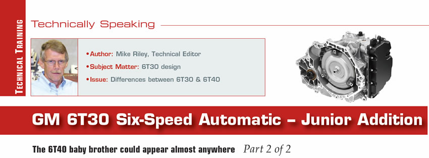
Drive/driven sprockets: The 6T30 utilizes the same drive mechanism as the 6T40, which is a drive-and-driven sprocket and chain. Unlike the Ford 6F35, the drive sprocket is a three-piece assembly consisting of the drive sprocket, park gear and output planetary drive hub (Figure 1). Although the drive hub caged bearing is the same diameter between both models, the bearing is narrower on the 6T30. The sprocket ratio on this particular unit is 1 to 1 since both sprockets have 40 teeth.
The design of the drive chain is common between both models although dimensionally the 6T30 is noticeably smaller especially in width (Figure 2).
When determining the width of the chain it’s always advisable to measure the sprocket width, not the outside surface of the chain. The sprocket width of the 6T30 is 0.750 inch whereas the 6T40 chain width is 1 inch.

Planetary sets: The 6T30 uses the same nested three-planetary-gear set design as the 6T40. The carrier arrangement provides a compact and efficient approach to overall transmission operation and has worked fairly well to date.
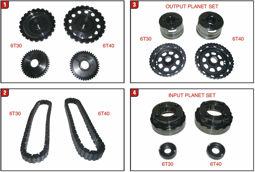
With the sprocket and chain assembly removed, the first planetary set to become visible is the output planet (Figure 3). As with most other internal components the planetary system is an octave lower than the 6T40. The output sun gear/shell is splined to and held by the 1-2-3-4 stationary brake. The output carrier, which is driven by the sprocket drive hub, is also splined to the reaction planetary ring gear. The output ring gear is attached to the input planet carrier.
The next planetary gear set in the lineup is the input planet assembly. The input planet is not directly connected to any stationary brake or rotating clutch. Size variation of the input-planet set between both models is comparable to the other gear sets (Figure 4). The input sun gear is splined to and driven by the input shaft and has the same identification mark as the 6T40 sun gear. The input planet ring gear is connected to the reaction planet carrier.
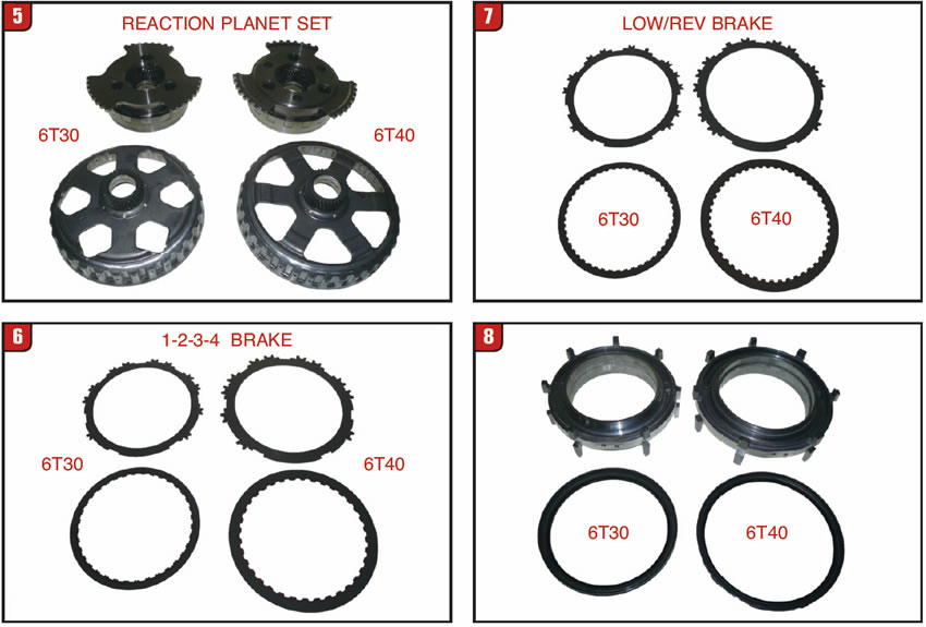
The final gear set in the stack-up is the reaction planetary. As with the other gear sets, the reaction planetary is noticeably smaller in the 6T30 than the 6T40 (Figure 5). The reaction planetary carrier can be held by two different components, one of which being the diode and the other the L/R stationary brake. In addition, the carrier can be driven by the 4-5-6 rotating clutch. The reaction sun gear/shell is held stationary by the 2-6 stationary brake or driven by the 3-5/R rotating clutch. It is the reaction sun gear and shell that takes the hit when the 3-5/R cushion spring bites the dust. As expected all related bushings and thrust bearings are smaller on the 6T30.
Stationary brakes/support: As with the other GM six-speed transmissions, the 6T30 has three stationary brakes, the 1-2-3-4, low/reverse and the 2-6 in that order front to back. Make sure to mark the backing plates, steel plates and cushion springs for position during disassembly.
After removing the big mutant tapered snap ring, the 1-2-3-4 stationary brake backing plate can be removed along with the frictions, steels and cushion spring. Not only is the 6T30 clutch pack smaller than the 6T40, other differences can exist (Figure 6). Attention must be paid as to whether the unit is equipped with GEN 1 or GEN 2 friction plates. Regardless of model the best way to tell a GEN 2 friction is by notches in the teeth, as illustrated by the 6T30 friction. The illustrated 6T40 friction is GEN 1. Pay special attention to the cushion spring that is almost identical to the L/R cushion spring which is thicker with a larger OD.
The L/R stationary brake is on the backside of the center support, and the friction tooth count is different from the other friction plates (Figure 7). The L/R friction plate’s spline to the outside of the diode inner race and the backing plate is positioned on top of the diode. The friction material is also different from the other plates. Make sure to mark the cushion springs to make sure of position and design.
The 6T30 aluminum center support is the same design used in the 6T40 and can cock just as easily in the case during removal (Figure 8). In addition to the apply holes are air bleed holes at the top of both model supports. Always ensure that they’re not plugged up. One difference between the supports is that the 6T30 uses the same piston and return spring on both sides, whereas the 6T40 support pistons and springs are different dimensionally.
Directly below the center support is the mechanical diode that is the OWC (one way clutch). As with other case components make sure to mark the diode before removal to make it easier to reinstall and use caution so as not to wedge the diode into the case. Although smaller, the 6T30 is pretty much a carbon copy of the 6T40 and also doubles as the 2-6 brake backing plate (Figure 9). The L/R backing plate must set flat against the front side of the diode.
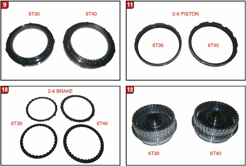
The third stationary brake is positioned at the bottom of the case and is designed somewhat different than the other two. The 2-6 stationary brake steel plate is substantially different between the 6T30 and 6T40 (Figure 10). As with the other friction plates, there is also the issue of whether the unit is GEN 1 or GEN 2, which can be identified by notches in the teeth. The 2-6 apply piston has cut outs to accommodate a noticeably larger return spring, which is not the norm (Figure 11). The 2-6 cushion spring is easily installed because there are no teeth to contend with and it does not have an upside.
Rotating clutch assembly: Probably the most troublesome component in GM six-speed automatics is the 3-5/R, 4-5-6 rotating clutch assembly, not to mention the design changes. Once the input shaft is out of the way the housing can be disassembled more easily.
As with just about everything else in the 6T30, the rotating clutch housing is smaller in design than the 6T40 (Figure 12). A couple of the lathe cut seals used for the 3-5/R apply piston are rather close dimensionally so make sure that the right ones be installed.
Upgrading the 6T40 from GEN 1 to GEN 2 involved the entire rotating clutch assembly, especially the 4-5-6 aluminum apply piston and bonded retainer (Figure 13). The 6T30 piston/retainer on the left is actually a GEN 2 design, whereas the 6T40 piston/retainer on the right is GEN 1. Note that the piston on the right has one extra seal groove in it because on GEN 2 applications that particular piston seal was moved to the housing. In addition, the GEN 1 bonded retainer on the right has a larger hole than the GEN 2 on the left. These changes impacted the 6T40 as well as the 6T30.
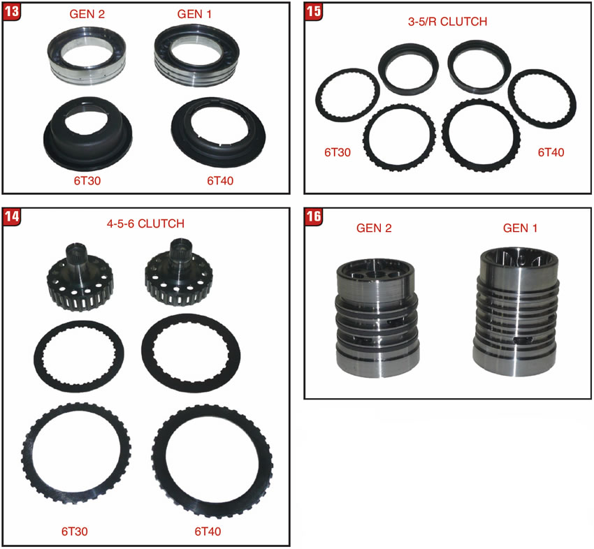
The 4-5-6 clutch pack components for the 6T30 are miniaturized just like everything else (Figure 14). To be consistent the GEN 2 frictions have notches in the teeth for identification. The 4-5-6 clutch hub splines to and drives the reaction planet carrier and bushing wear is not uncommon. The last and for that matter the most vulnerable clutch pack in the unit is 3-5/R due to the infamous cushion spring failure, although not as pronounced on 6T30 models. It is also the only clutch pack that the external teeth are on the friction plates and internal teeth on the steel plates. Even the apply piston is somewhat backwards (Figure 15). Changes have certainly occurred with this assembly.
One item that is same between 6T30 and 6T40 models is the sealing ring support that bolts to the back of the case (Figure 16). Unfortunately, the ring support got switched from a four ring design to a three ring design when upgrading from GEN 1 to GEN 2. The rotating clutch housing and sealing ring support must be the same design level regardless of transmission model.
Currently, the transmission repair action has been primarily with the GM 6T70 and secondly the 6T40; however, as time goes on the 6T30 transmissions will make an entrance, so saddle up. The only other question is what about Ford.


