
Technically Speaking
- Author: Wayne Colonna, Technical Editor
Understanding operation of planetary gearsets helps in noise diagnosis
Thirty years ago I was in a trade school learning the operation of transmissions. I remember some of the students commenting on how studying planetary rotation was as exciting as watching paint dry on a wall.
Well, I thought to myself that this must mean it doesn’t take much to amuse me, as I found understanding the operation of planetary gear sets to be intriguing. I do admit that it doesn’t make for the best bedtime reading, but I did see the importance of learning it. Let me explain.
Our instructor began by teaching us that a simple planetary gear set consists of 1) a center sun gear, 2) a carrier with three or more pinion gears that are free to rotate on their pins around the sun gear and 3) the internal ring gear, which meshes with the pinion gears. Then he started to say, “If you hold the internal gear stationary and drive the sun gear, you will see the pinions drive the carrier in the same direction as the sun gear but at a reduced speed with increased power.” This is where some of my fellow classmates started to get bored.
He continued: “If we switch this around and now the center sun gear is held and the turning effort is applied to the internal gear, this drives the carrier through the pinions in the same direction as the internal ring gear but at a reduced speed of the internal ring gear in a reduction not as low as the previous but still with increased power.”
By this time I could hear some heavy breathing somewhere in the classroom, the type you hear before a good snore. The instructor continued to explain that these are simple examples of a first-gear and then a second-gear ratio. He then went on to say that if both the sun gear and the internal ring gear were driven in the same direction at the same speed, the whole planetary assembly became locked in 1:1 ratio.
Needless to say, most of the guys were “sleep drooling” past their hands and into their class materials, and so they never even heard how reverse is achieved. That was the grand finale of the night!
OK, so where am I going with this? Through the years of being on the tech line diagnosing problems, I have come to appreciate understanding planetary rotation when it comes to diagnosing noise.
A great example of this is the Mercedes 722.6 transmission, which has three planetary sets. In first gear, all three are in a reduction mode. When the 1-2 shift takes place the front planet locks 1:1 while the other two remain in reduction. If the noise disappeared on the 1-2 upshift, I knew the noise was somewhere in the front planetary. When a 2-3 shift takes place, the rear planetary locks 1:1, so if the noise disappears then, the rear planet is suspect. When a 3-4 shift takes place, the center planet locks 1:1, so if the noise disappears then, the center planet is suspect. When a 4-5 shift takes place, the front and rear planetaries work together to overdrive the center planetary, which is connected to the output shaft.
My point here is that when you take the time to go through the planet system “once” determining which and when planets are in reduction, overdriven or locked 1:1, you rarely have to go back and think it through again. With the 722.6, I would rarely have the need to break my head thinking through what is turning and holding because of already knowing what I have just explained.
As an additional benefit from taking the time to think this through, I also saw that the N3 Hall-effect speed sensor in the conductor plate reads the rotation of the K1 clutch drum, with which the front sun gear is integral. So I know that the front sun gear is held in first and fifth, which explains why one would not see an N3 speed-sensor signal in first and fifth gears but there would be a reading in 2nd, 3rd and 4th gears.
I recently had to put myself into the AF23/33-5 (AW55-50) transmission used in the Saturn Vue and Ion sedan as well as various Volvo vehicles. This transmission caught my attention for two reasons: First, it is the only passenger car transmission I know of in which the first-gear ratio (4.68) is lower than reverse (3.18). What also fascinated me is that this is truly a five-speed but fifth gear is 1:1.
I mentioned this at our San Francisco seminar, and a gentleman came up afterward and said he saw this as well, and he mentioned how the final drive had such tall gears in it. In fact, the final drive has a 2.44 ratio. With this configuration we can see that less torque and higher engine speeds is what the engineers had in mind in this powertrain package.
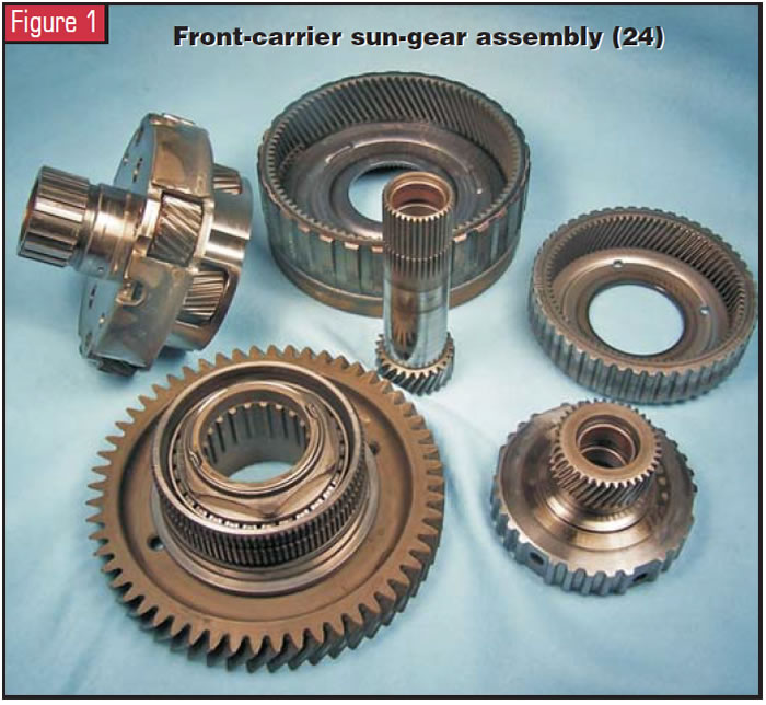
But getting back to the transmission, this AF23/33-5 sports three planetary gear sets, as you can see in figures 1 and 2. GM calls the planetary set shown in Figure 1 the front-carrier sun-gear assembly (gear set #24).
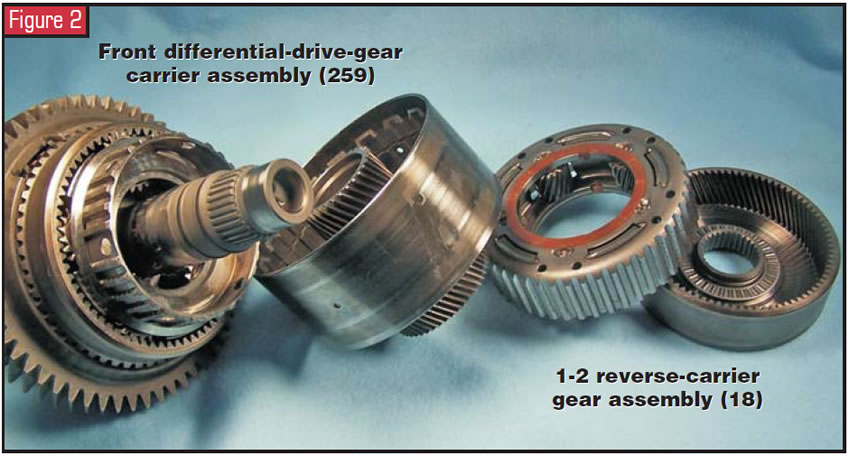
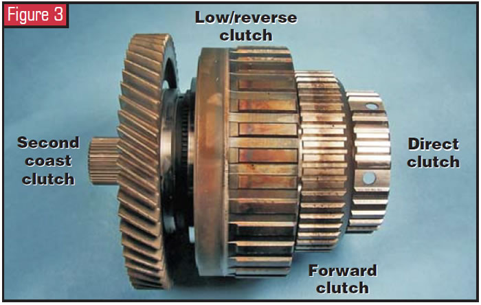
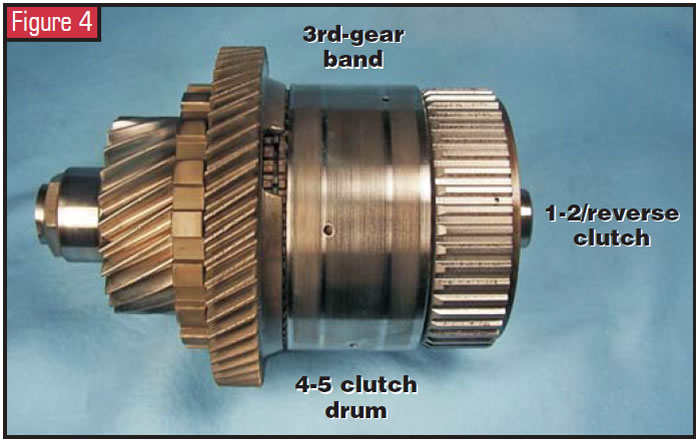
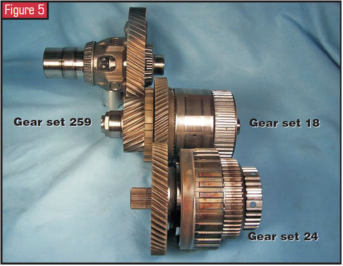
GM calls the middle and rear planet assemblies, as I refer to them (see figure 2), the front differential-drive-gear carrier assembly (gear set #259) and the 1-2 reverse-carrier gear assembly (gear set #18). Figures 3 and 4 show these gear sets fully assembled with most of the driving and holding elements identified. Figure 5 illustrates how the whole gear train meshes, including the differential.
When I look at the assemblies in this fashion and compare this with an application chart, I can quickly identify what each planetary gear set is doing in each gear. I then make myself a chart that tells me which planetary set is in a low reduction, a lesser reduction, a locked 1:1 gear set or an overdriven gear set. From this chart I can quickly identify possible noise locations. Figure 6 is a chart I have made for this transmission.
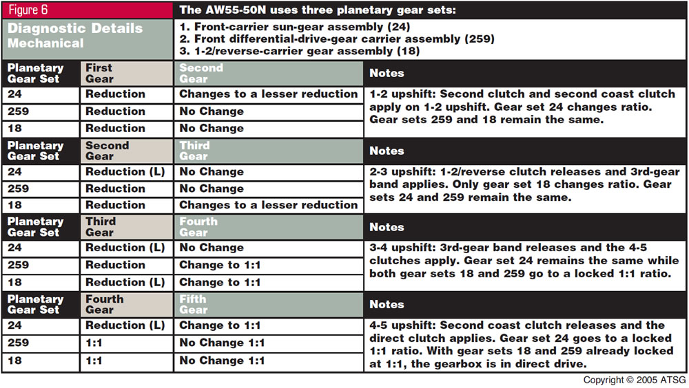
The chart shows that in first gear all three planetary sets are in a reduction. When a shift into second occurs, only planetary gear set 24 changes ratios to a lesser reduction. The other two remain the same. So if we had a noise that changed pitch on the 1-2 upshift, we could be looking at this planetary gear set as being the problem. When a 2-3 shift occurs, only gear set 18 changes ratios to a lesser reduction. So if we had a noise that changed pitch on the 2-3 upshift, we could be looking at this planetary gear set as being the problem. When a 3-4 shift occurs, both gear sets 18 and 259 lock 1:1 but gear set 24 remains in ratio. When a shift into 5th gear takes place, this gear set locks 1:1, putting the gearbox in direct drive. So if a noise changed pitch on the 1-2 upshift and disappeared with the shift into 5th, gear set 24 is a sure bet.
As you can see, once you think through the planetary gear sets and place them into a chart like the one I did in Figure 6, it becomes easier to know which planetary set could give you noise. It is a process of elimination.
Another benefit that comes when you understand power flow in this fashion is that you will never have to be concerned about the direction of any one-way holding devices. You will know, because you will understand when such a device holds a member in the planetary gear set or assists in driving it. From that understanding, you can determine the lock direction and freewheel direction of any one-way holding device.
You also will begin to see how many units hold a sun gear to achieve 2nd and 4th gears and drive the same sun gear for reverse. This also helps you to diagnose. Take, for example, a very old problem we experienced with a 604 transmission. The sun gear would break at the weld and there would be no reverse. It would take off in first gear and shift into neutral, as the sun gear couldn’t hold. Since failsafe is second gear, you stopped moving until you cycled the ignition and the whole process repeated itself.
Again, the benefits are there when you take the time to think a unit through and make a chart so you can use it as a quick means to diagnose a problem. And if you are a true gear head, you will see this article as a good bedtime read – if you haven’t fallen asleep already.


