Up To Standards
- Author: Mike Weinberg
- Subject Matter: Types of four-wheel drives
- Issue: Replacing a pinion gear
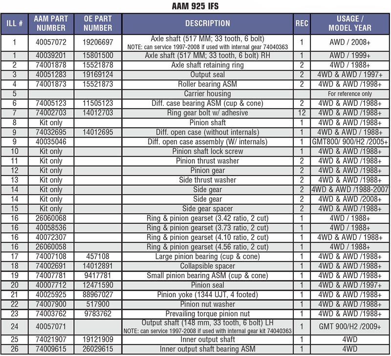
Salisbury & Split-Case Front Drive Axles
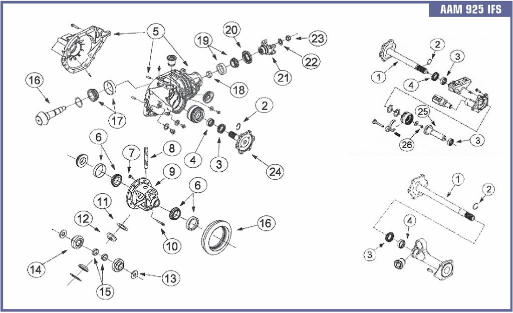
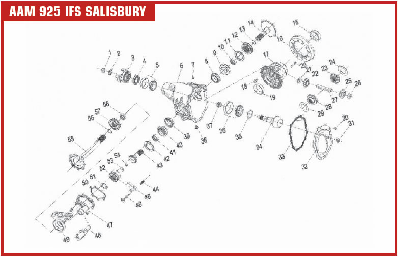
2011 and later GM trucks equipped with four-wheel drives will be found with three different types of IFS (independent front suspension) front drive axles. There is an 8.25” ring gear and two different 9.25” ring gear front axles. The 8.25” and one of the 9.25” axles are the “suitcase” type of design using two aluminum case halves that bolt together containing the ring and pinion, differential carrier and other components. The other 9.25” unit is a Salisbury (Spicer design) with a one-piece case with a removable case cover, which is used in the 2500 and 3500 HD models. The aluminum split case design has been in use for many years and the 9.25” Salisbury type was introduced in 2011.
There are two types of drive models, full-time four-wheel drive (F4WD) and selectable front-wheel drive (SFWD). On the full-time unit the drive axles are locked to the differential and there is no disconnect system, so the front drive shaft is constantly driving the front axles, and 4WD is controlled only through the transfer case. On the selectable front axles, there is a disconnect system that permits the front wheels to turn without power flow through the differential in the 2WD mode.
The transfer-case control module sends a signal to an electric motor actuator located on the axle housing that, when the plunger is extended, operates a fork and sliding sleeve to bind the two axles together and locking the differential into 4WD. When the shafts are locked together, the drive axle performs like a semi-floating rear. The differential is open (no limited slip, which allows different speed rates between the two axles to eliminate tire scrub and wheel hop in the corners. The front axles are able to handle the suspension travel with CV joints on both ends and are connected to a wheel shaft.
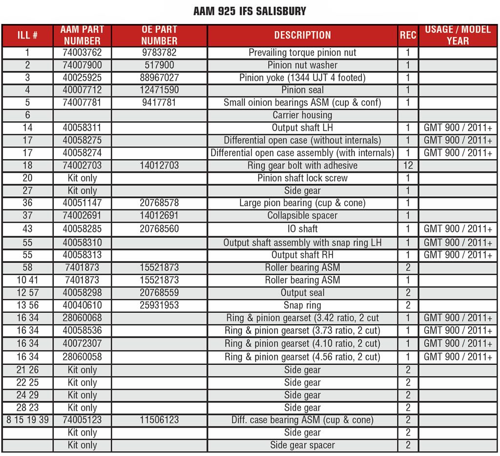
The Salisbury type rear (Spicer) has been around forever as a rear drive axle. Some designs used threaded adjusters to set the carrier bearings and backlash, and some use selective shims. Some designs used a case that had to be spread by tools in order to remove the ring gear and carrier. The design is stronger than the split case aluminum units for HD use.

Rebuilding these units are the same as other ring and pinion setups with pinion depth, carrier alignment, and proper backlash being critical to obtain a quiet, durable repair. One of the key tools to have is a pinion depth gauge, which makes setup foolproof, due to the many variations of ring and pinion sets being sold in the market. Face-milled and face-hobbed gear sets will require different backlash settings.
I have written several articles in this magazine describing the different procedures necessary. If you are replacing a pinion gear that is face milled or hobbed with the identical gear cut, you can re-use your original pinion shim with good results. If the gear set is of different manufacture you will need the pinion depth gauge to get it right. Kent Moore makes a gauge set for these units that is Part #J34925. They cost a few bucks but will save you time in getting it right and possibly a new gear set. You will also need a 57MM 12 point socket to adjust the threaded adjusters for the diff carrier positioning. Another basic tool to have for any rear end repairs is a set of “setup bearings.”
Buy two sets of carrier and pinion bearings when ordering parts. Take one set of bearings and, using a brake hone of other method, take out the 2 or 3 thousandths of interference fit inside the bearing bores so they slip on. Use these bearings to set up the rear and when your backlash and pattern are correct, slip them off and install the new bearings and the job is complete. The slip-on bearings make changing shims a snap and avoid cage breakage and other issues that occur when changing shims. Label and save the setup bearings for the next unit that you work on. If you price the job correctly the tools are paid for.