Front-Seal Blowout after Converter Replacement in 09D/T Transmissions - Transmission Digest

Front-Seal Blowout after Converter Replacement in 09D/T Transmissions

The Aisin AW TR-60SN/VW 09D/T transmissions are found in the 2002-2010 VW Touareg and the 2003-2010 Porsche Cayenne. There have been reports of the front seal blowing out after the torque converter and related parts have been replaced. The root cause of the seal blowing out is the buildup of pressure because the drain-back passage that normally vents the area behind the front seal is blocked. This area is normally vented through the stator support/pump cover. The seal-blowout issue occurs when the pump (body and gears) is mated to an incorrect stator support (pump cover) and blocks the drain-back passage. To understand how easy it is to make this mismatch, you need to know the large number of possible combinations. Be aware that the seal-blowout problem is only one of several issues that you can create if you mismatch components.

Front-Seal Blowout after Converter Replacement in 09D/T Transmissions

Torque Converter Tech Tips

Subject: Front-seal blowout after replacement of torque converter and related parts
Unit: AW TR-60SN/VW 09D/T
Vehicle Applications: 2002-10 VW Touareg, 2003-10 Porsche Cayenne
Essential Reading: Rebuilder, Diagnostician
Author: Marc van Aalderen

Torque Converter Tech Tips

  • Subject: Front-seal blowout after replacement of torque converter and related parts
  • Unit: AW TR-60SN/VW 09D/T
  • Vehicle Applications: 2002-10 VW Touareg, 2003-10 Porsche Cayenne
  • Essential Reading: Rebuilder, Diagnostician
  • Author: Marc van Aalderen

The Aisin AW TR-60SN/VW 09D/T transmissions are found in the 2002-2010 VW Touareg and the 2003-2010 Porsche Cayenne. There have been reports of the front seal blowing out after the torque converter and related parts have been replaced.

The root cause of the seal blowing out is the buildup of pressure because the drain-back passage that normally vents the area behind the front seal is blocked. This area is normally vented through the stator support/pump cover. The seal-blowout issue occurs when the pump (body and gears) is mated to an incorrect stator support (pump cover) and blocks the drain-back passage. To understand how easy it is to make this mismatch, you need to know the large number of possible combinations. Be aware that the seal-blowout problem is only one of several issues that you can create if you mismatch components.

The first thing you will find is that the vehicles with the smaller engines have a torque converter with a single lockup clutch, and the vehicles with the larger engines have a clutch-pack-type lockup clutch similar to that of the Mercedes 722.6. The torque-converter-clutch (TCC) circuit for the single-clutch converter uses the conventional two-path lockup hydraulics in which the converter charge/TCC release oil enters the converter through the input shaft. The clutch-pack style of this converter uses a three-path hydraulic lockup in which the TCC apply oil enters the converter through the input shaft.

Because of the differences in the two- and three-path hydraulic circuits, many of the related parts are different. The input shaft for the two-path lockup circuit is smaller in diameter and has three sealing rings; the larger-diameter input shaft used with the three-path circuit has four sealing rings. These shafts are not interchangeable. The valve bodies for the two- and three-path units also are different.

Mismatching the valve bodies will either result in no lockup or cause the engine to stall as soon as the vehicle is placed into gear.

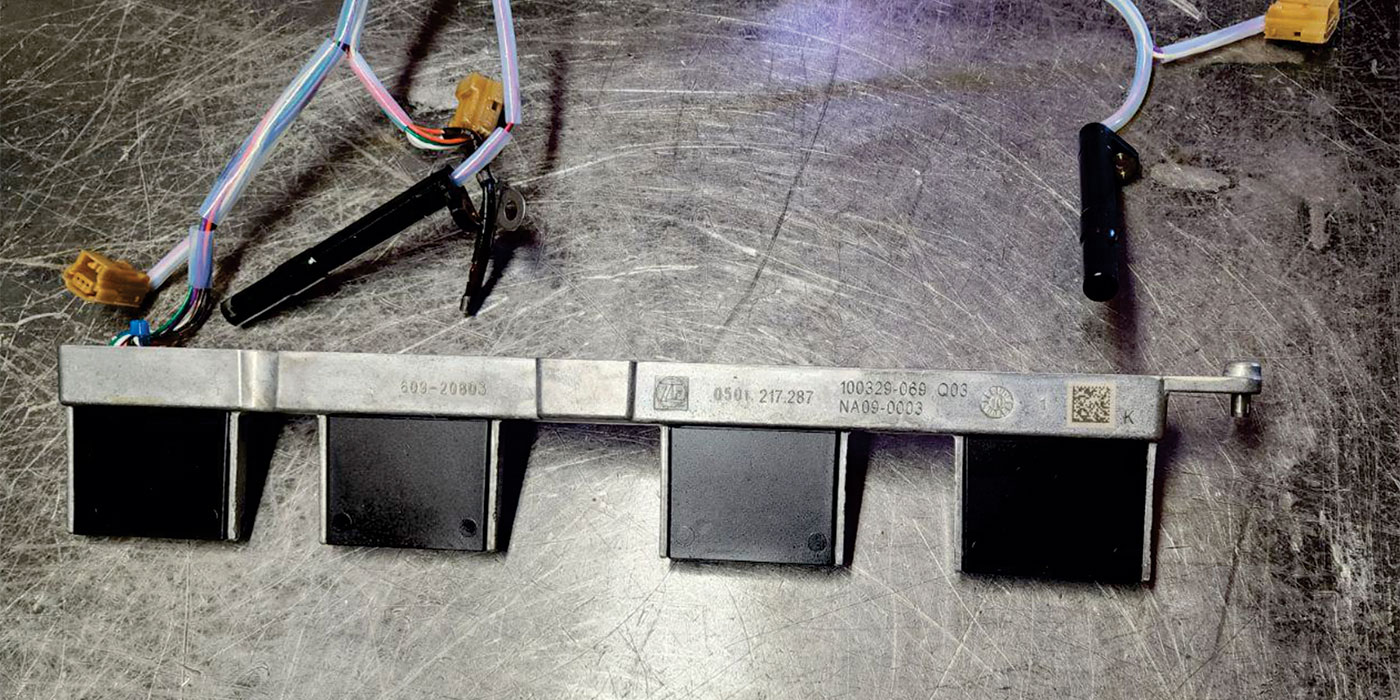
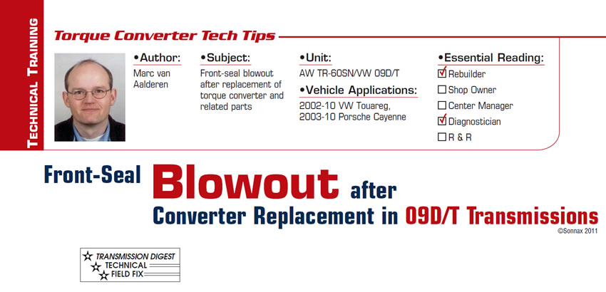
If this was not confusing enough, there is an early bushing-style pump and a late-model needle-bearing-style pump for both two- and three-path units. To make matters even worse, the bushing- and bearing-style pumps use a different outside diameter on their respective converter impeller hubs. The bushing-style hub (Figure 1) is the same 45.15mm (1.778 inches) for its entire length, while the bearing-style hub (Figure 2) is 44.95mm (1.770 inches) and steps down to 44.30mm (1.744 inches) where the pump gears ride.

The early bushing-style converters can be upgraded to the late-model bearing style by simply replacing the impeller hubs.

Since the early bushing-style pumps have a high failure rate, they are not as desirable or readily available. Upgrading to the bearing-style pump is a common practice, but this is where the mismatch occurs that causes the seal to blow out.

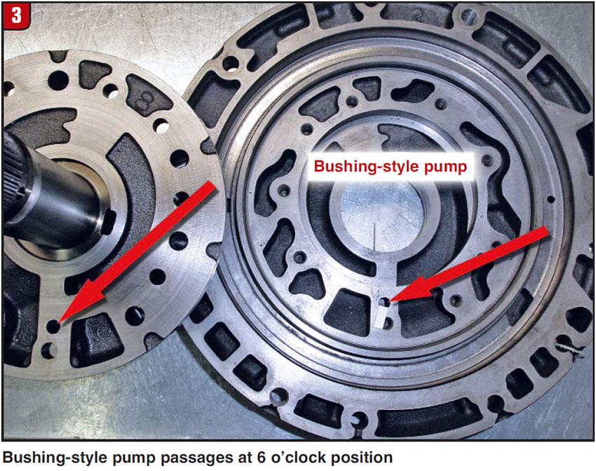
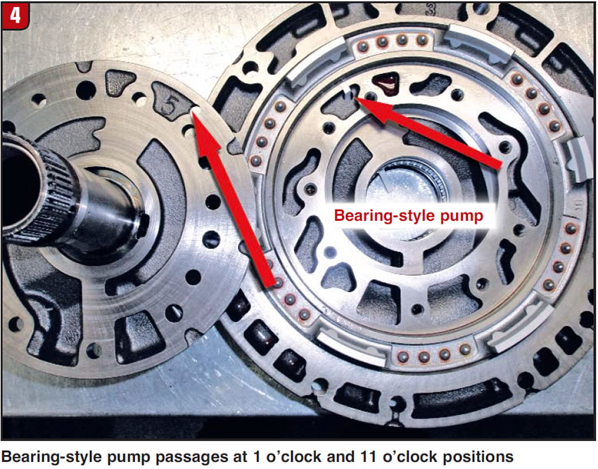
The early bushing-style pumps (Figure 3) have the drain-back passage at the 6 o’clock position, and late-model bearing-style pumps (Figure 4) have drain-back passages at the 1 o’clock and 11 o’clock positions.

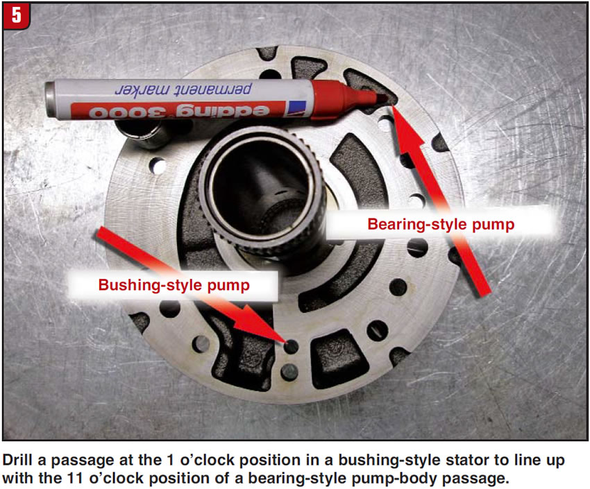
When you are mating a late-model pump to an early-model stator support/pump cover, you must drill the stator support so that the drain-back passage continues through and lines up with the pump-body passage (Figure 5).

If you are not replacing the pump assembly as a unit, always be alert to the possibility of a blocked drain-back passage.

Marc van Aalderen is production manager at Valve Body Xpress, Europe. Valve Body Express is a member of the Sonnax TASC Force™ (Technical Automotive Specialties Committee), a group of recognized industry technical specialists, transmission rebuilders and Sonnax Industries Inc. technicians.

©Sonnax2011

You May Also Like

Sherlock Holmes Approach to an AB60 No-Move Situation

The effectiveness in diagnosing automatic transmission malfunctions is an art form. Although there are similarities among the wide varieties of transmissions on the road, each transmission has its own peculiarities. Aside from having mechanical, hydraulic, and electrical hardware systems to contend with, software/programming issues and various vehicle platforms make diagnostics much more difficult.  Using scopes provides

ab60

The effectiveness in diagnosing automatic transmission malfunctions is an art form. Although there are similarities among the wide varieties of transmissions on the road, each transmission has its own peculiarities. Aside from having mechanical, hydraulic, and electrical hardware systems to contend with, software/programming issues and various vehicle platforms make diagnostics much more difficult. 

GM 6T40 Pump Identification Guide

The 6T40 was introduced in 2008 for General Motors front-wheel-drive cars in the Chevrolet Malibu and has gone through several changes throughout its three generations, specifically in the pump area. The 6T40 is closely related to the more lightweight 6T30 and the heavier duty 6T45 and 6T50. Generation one started phasing out during the 2012

Seeing the Forest AND the Trees

They say that the proverbial phrase “I couldn’t see the forest for the trees” means that a person or organization cannot see the big picture because it focuses too much on the details. Related Articles – 4L60E Harsh 1-2 Shift – TASC Force Tips: Diagnosing 8L45 & 8L90 Shift Complaints – TASC Force Tips: Hydraulics

The Manifold Pipeway

The Honda six-speed transmission has been on the bench of many specialty shops for one reason or another (figure 1). But, for those of you who have yet to lay your hands on one, mounted on the upper side of the unit is one of the largest, if not the largest solenoid and pressure switch

8L90 Vacuum Testing

Below are the diagrams for vacuum testing GM 8L90 transmissions. Note: OE valves are shown in rest position and should be tested in rest position unless otherwise indicated. Test locations are pointed to with an arrow. Springs are not shown for visual clarity. A low vacuum reading indicates wear. For specific vacuum test information, refer

Other Posts

Shift Pointers: Shift rod displacement in a luxury car

When owning a luxury vehicle, one cannot be faint-hearted when the time comes to pay a repair bill. Even if you bought a used luxury car at a very good price, this doesn’t change the price of new components required to make that repair. Related Articles – Don’t fear customer complaints about CVTs – 2024

Critical Wear Areas & Vacuum Test Locations for FORD 6R80/6R100

Note: OE valves are shown in rest position and should be tested in rest position unless otherwise indicated. Test locations are noted with an arrow. Springs are not shown for visual clarity. Low vacuum reading indicates wear. For specific vacuum test information, visit www.sonnax.com. Related Articles – Hydraulics Fundamentals: Shift & Relay Valves – Another

Hydraulics Fundamentals: Shift & Relay Valves

Shift valves and relay valves share a lot of the same duties. This article is one of a series by Sonnax exploring how valves and hydraulic circuits work and what results when they quit functioning correctly.

Another 62TE ‘No-Move’ Possibility

Most seasoned techs have several quick diagnostic steps they take when faced with a transmission malfunction. The type of problem and transmission determines which steps to take. For example, a “no-move” condition. Related Articles – Shift Pointers: A Chrysler 300 no-shift complaint – A guide to common GM, Ford and Nissan programming issues – Shift