Ford 4F27E Shift Strategy – a Different Way of Doing Things - Transmission Digest

Ford 4F27E Shift Strategy – a Different Way of Doing Things

The 4F27E transmission uses two on/off solenoids and three PWM solenoids to produce each of the shifts and converter-clutch apply, as the chart in Figure 1 shows. The EPC solenoid is used to control line pressure relative to engine torque. So far this sounds easy, but from a strategy standpoint, it progressively moves toward a “different way of doing things” when compared with what we are accustomed to.

Ford 4F27E Shift Strategy – a Different Way of Doing Things

Technically Speaking

Author: Wayne Colonna, Technical Editor

Technically Speaking

  • Author: Wayne Colonna, Technical Editor

The 4F27E transmission uses two on/off solenoids and three PWM solenoids to produce each of the shifts and converter-clutch apply, as the chart in Figure 1 shows. The EPC solenoid is used to control line pressure relative to engine torque. So far this sounds easy, but from a strategy standpoint, it progressively moves toward a “different way of doing things” when compared with what we are accustomed to.

Let’s start off on familiar ground. Shift solenoids A & B are the on/off solenoids that, when they are off, block fluid from stroking valves. The pulse-width-modulated solenoids, C, D & E, are the opposite. When they are off they allow fluid to pass through the solenoid and stroke valves. OK, so far, not so bad. Sounds a little like the Chrysler 41TE/42LE transmissions with their normally applied and normally vented PWM and on/off solenoids.

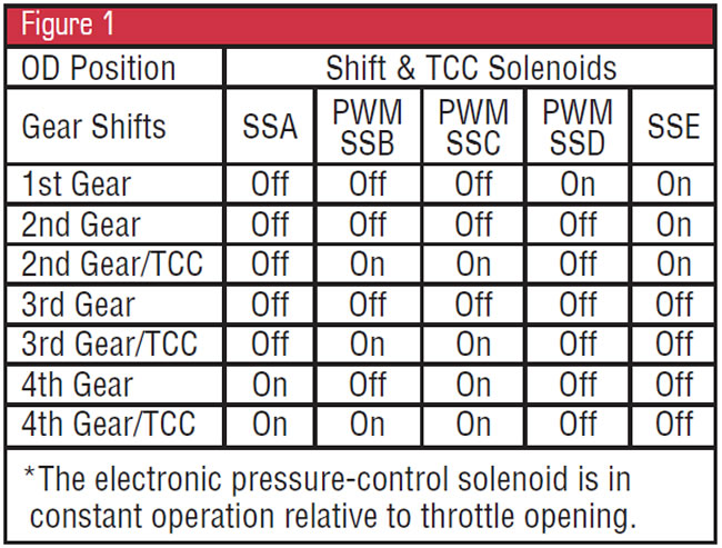
The first departure from the “norm,” if you will, is that shift solenoid B could be better understood as a lockup/TCC solenoid. To call this shift solenoid B made it difficult for me when I first looked at a solenoid-application chart like the one in Figure 1. I kept thinking it was a gear-shift solenoid, not a TCC shift solenoid. But now, having clarified the operation of shift solenoid B, it would be good to do a “simple” overview of the function of each of the other “shift” solenoids. Doing so will make the solenoid-application chart considerably more understandable.

  • SSA – When this solenoid is in the on position, it strokes the 3-4 shift valve, which exhausts forward-clutch and servo-release pressure.
  • SSB – When this solenoid is in the on position, it strokes the TCC control valve, which exhausts the converter-release pressure, allowing for TCC apply.
  • PWM SSC – When this solenoid is in the off position, it provides forward-clutch apply pressure.
  • PWM SSD – When this solenoid is in the off position, it provides servo-apply pressure.
  • PWM SSE – When this solenoid is in the off position, it provides servo-release pressure.

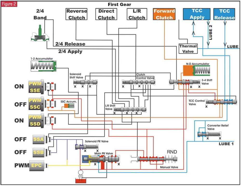
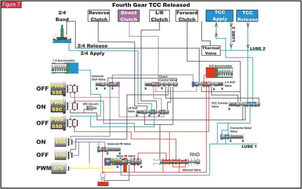
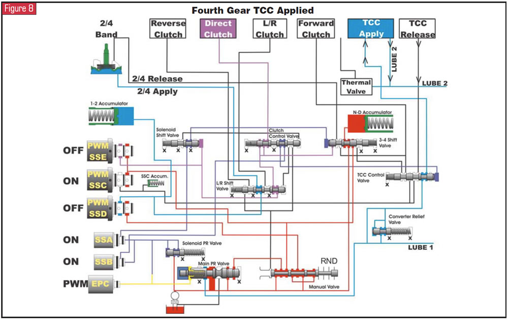
With this simple overview of the function of each of the shift solenoids, along with the hydraulics provided for each of the shifts while the manual valve is in the D4 position (figures 2-8), a closer look will provide a more-detailed understanding of “a different way of doing things.”

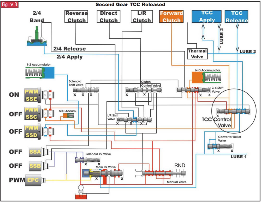
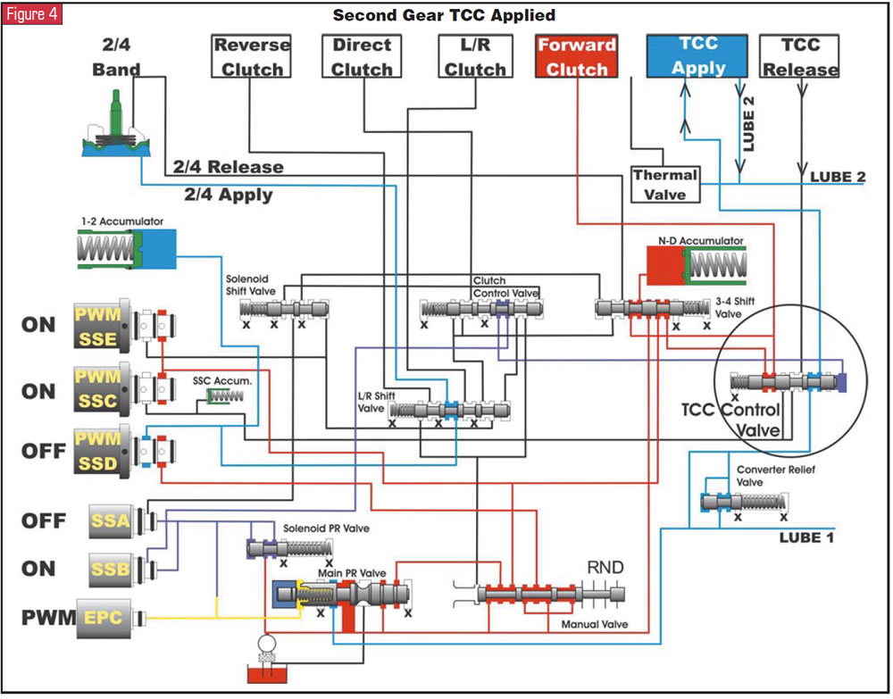
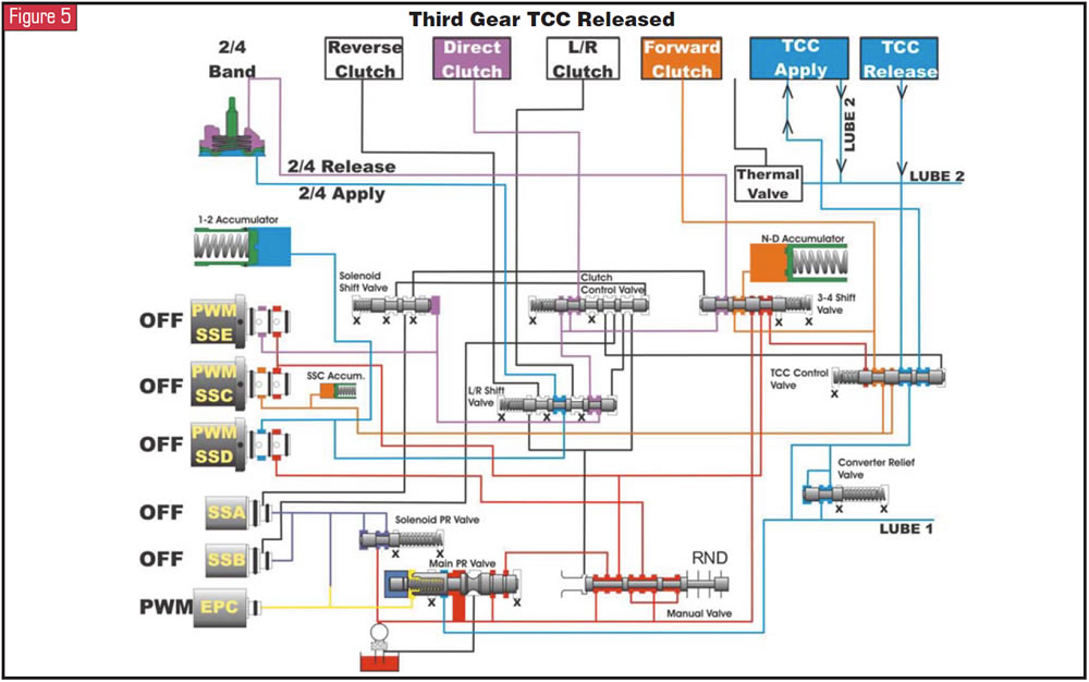
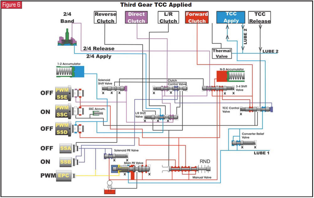
Using the second-gear TCC-off hydraulic provided in Figure 3, carefully look at the TCC control valve. Notice that forward-clutch oil runs through the valve from the PWM SSC to the forward clutch. Also notice that line pressure is routed to and blocked by the TCC control valve’s land next to the spring. When this TCC control valve is stroked by SSB for lockup, TCC-release oil becomes connected to the PWM SSC solenoid for a controlled TCC apply. At the same time, the forward-clutch apply oil switched from being fed by the PWM SSC solenoid to the line pressure that was being blocked by the land next to the spring (see Figure 4). Now that is a different way of doing things!

So the PWM SSC controls not only forward-clutch apply but also converter-clutch-apply feel. Should this solenoid malfunction mechanically, we could have a harsh apply or delayed apply into forward and no TCC, or a slipping-TCC concern. It is obvious that if SSB malfunctioned, we would experience TCC-apply issues as well. And looking at the TCC control valve, in theory should the valve or the valve bore develop excessive wear, combined with a lazy stroke of the valve, a forward-clutch slip could occur at the time TCC is being applied in second or third gear.

You May Also Like

Sherlock Holmes Approach to an AB60 No-Move Situation

The effectiveness in diagnosing automatic transmission malfunctions is an art form. Although there are similarities among the wide varieties of transmissions on the road, each transmission has its own peculiarities. Aside from having mechanical, hydraulic, and electrical hardware systems to contend with, software/programming issues and various vehicle platforms make diagnostics much more difficult.  Using scopes provides

ab60

The effectiveness in diagnosing automatic transmission malfunctions is an art form. Although there are similarities among the wide varieties of transmissions on the road, each transmission has its own peculiarities. Aside from having mechanical, hydraulic, and electrical hardware systems to contend with, software/programming issues and various vehicle platforms make diagnostics much more difficult. 

GM 6T40 Pump Identification Guide

The 6T40 was introduced in 2008 for General Motors front-wheel-drive cars in the Chevrolet Malibu and has gone through several changes throughout its three generations, specifically in the pump area. The 6T40 is closely related to the more lightweight 6T30 and the heavier duty 6T45 and 6T50. Generation one started phasing out during the 2012

Seeing the Forest AND the Trees

They say that the proverbial phrase “I couldn’t see the forest for the trees” means that a person or organization cannot see the big picture because it focuses too much on the details. Related Articles – 4L60E Harsh 1-2 Shift – TASC Force Tips: Diagnosing 8L45 & 8L90 Shift Complaints – TASC Force Tips: Hydraulics

The Manifold Pipeway

The Honda six-speed transmission has been on the bench of many specialty shops for one reason or another (figure 1). But, for those of you who have yet to lay your hands on one, mounted on the upper side of the unit is one of the largest, if not the largest solenoid and pressure switch

8L90 Vacuum Testing

Below are the diagrams for vacuum testing GM 8L90 transmissions. Note: OE valves are shown in rest position and should be tested in rest position unless otherwise indicated. Test locations are pointed to with an arrow. Springs are not shown for visual clarity. A low vacuum reading indicates wear. For specific vacuum test information, refer

Other Posts

Sometimes, a diagnostic code is all you need

With ATSG having the opportunity to help shops solve problems, sometimes we get faced with some real doozies. A shop will call and give us a laundry list of DTCs, leaving us to think someone must have a bulkhead connector unplugged. We then go through the arduous task of deciding which codes prompted other codes

10L80 and 10R80 pump gear differences

You may have seen an article in the August 2023 issue of Transmission Digest called “GM 10L80: A new kind of pump noise,” which goes over how the front cover housing in the 10L80 is fitted with a converter drive gear and idler gear. The idler gear drives the pump’s driven gear, and is press

Spotting different 68RFE designs through the years to avoid issues

The Chrysler 68RFE has had several changes through the years. Its four-speed predecessor began with a noisy solenoid pack identified by a black colored pass-through case connector (seen in Figure 1).  Related Articles – A guide to common GM, Ford and Nissan programming issues – Shift of the shaft: Diagnosing Chrysler 48RE manual shaft issues

Sometimes, you should sweat the small stuff

It’s a common phrase: There may have been a time when you worried about something, and someone who knew what you are going through said, “Hey, don’t sweat the small stuff.” Sometimes, this may be good advice. But other times, it may be wise to handle the small stuff before it becomes bigger “stuff.”  Related