Torque Converter Tech Tips
- Author: Ed Lee
In a torque converter the friction material most often used on a lockup piston or cover is a mix of fibrous materials in a phenolic resin. The adhesive used to bond this material to steel is also phenolic based. Phenolic is a thermo-set type of plastic, and this plastic has unique properties.
Many plastics are just long strands of molecules. When these plastics are heated, the strands untangle and the plastic becomes soft or even melts. Phenolics, on the other hand, form solid links in all directions when heated. Once these links are cured, they remain connected when the plastic is heated or cooled, and the plastic cannot be re-melted. This makes phenolics particularly suitable for high-temperature environments, where high strength is needed (e.g., bonding lockup clutches in torque converters.)
Typically, a bonding machine is used to bond the friction material to the piston or cover. The bonding machine uses a combination of pressure and heat to cause the adhesive to cure. Most bonding adhesives need to reach a temperature of 400-425° F and need to be compressed by a pressure of 200 pounds per square inch of friction material to be fully cured.
The 400-425° F temperature needs to be reached at the bond line. The bond line is the area where the adhesive on the friction material meets the steel surface of the piston or cover. Remember that the temperature-controller setting on the bonder is not the same as the bond-line temperature. The temperature-controller setting is the temperature available at the heating element. From the lower heating element, the heat must pass through the bottom bonder plate and the piston to get to the bond line. From the upper heating element, the heat must pass through the top bonder plate and the friction material to get to the bond line.
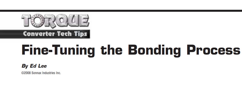
The rates at which the friction material and the pistons transfer heat vary dramatically and must be treated accordingly. The world-class Allison pistons with friction material on both sides take almost twice the bond time as a similar one-sided piston. Friction material that is 0.070 inch thick will take longer to bond than the same material in a 0.040-inch thickness. Bond times also vary by the composition of the friction material. Paper-based friction materials, including composites with Kevlar, are better insulators and will typically take up to one more minute of bond time than the same thickness of high-carbon or spun-woven materials.
The first factor to influence your temperature setting will be your bonder setup. It is easy to see that the size or mass of the plates required for the converter being bonded dictates your initial heat setting. It is not as obvious, but it is equally important to remember that the makeup of the damper assembly also has an impact on the rate of heat transfer. The different 298mm damper designs (see Figure 1) will have up to one minute difference in their bonding times.
Even the thickness of the piston will affect bonding times. The more material that is machined off a piston, the faster the piston will transfer heat. Since the rebuilder does not know how many times a piston has been machined, a minimum-thickness check is a good safeguard. If you are bonding a batch or large run with the same plate setup, start off with the pistons with the slowest rate of heat transfer or longest bonding-time requirement.
Flow zone
The phenolic adhesive starts on the friction material and must transfer (flow) to the piston or cover for a good bond. As the adhesive is heated, it goes from a solid state to a liquid state and then back to a solid state as it cures. The time that the adhesive is in its liquid state is called the “flow zone.” The flow zone will vary from adhesive to adhesive, but the typical phenolic adhesive used for bonding will have a flow zone of 200-300° F.
The best bonding results occur when the adhesive is in its flow zone for 45 to 90 seconds. One minute is a good target time when you’re adjusting your flow-zone time. A shorter time does not allow enough adhesive flow, resulting in a weaker bond. An overly long time allows the adhesive to flow out of the bond line or penetrate excessively into the paper, again resulting in a weaker bond.
When you are adjusting the length of the flow zone, it is best to limit your changes to the bottom temperature controller and bottom plate. The reason for not making temperature changes to the top controller is the thermal limit of most friction materials. Since cotton is a component of ALL paper-based friction materials, it will start to scorch and deteriorate at 440° F. For that reason the top plate should not be set higher than 425° F. The only exception to this rule would be if there is a friction ring bonded to the top plate, preventing direct contact between the top plate and the friction material being bonded. The bottom temperature controller can be set to a higher temperature, because the bottom plate does not come into direct contact with the friction material.
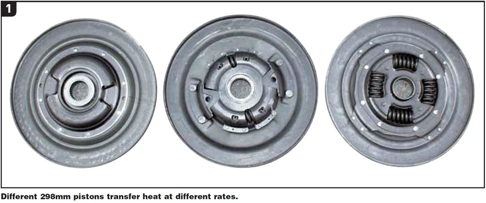
Setting the temperature too high for the heat-transfer rate of some pistons in your batch may cause the flow zone time to dip below the 45-second minimum. To lengthen the flow-zone time, install a friction ring to the bottom plate. The thicker (0.070-inch) paper-based friction material will lengthen the flow-zone time the most, and the thinner (0.040-inch) carbon-based (high-carbon, and spun-woven) friction material will lengthen the flow-zone time the shortest amount. This trick allows you to make minor adjustments that will keep you in your zone without major alterations to your base setup (see Figure 2).
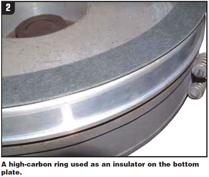
To monitor the temperature and times for a good bond, a thermometer with a handheld probe is a good investment (see Figure 3). Position the probe as close to the bond line as possible. If you don’t have a good thermometer, you may want to consider using a non-reversible temperature liquid or temperature crayon to monitor your bonding setup. The temperature liquids and crayons are available in the McMaster-Carr and MSC catalogs.

Ed Lee is a Sonnax Technical Specialist who writes on issues of interest to torque converter rebuilders. Sonnax supports the Torque Converter Rebuilders Association. Learn more about the group at www.tcraonline.com.


