


A customer with a 2009 Chevy Tahoe equipped with a 2ML70 (two-mode) hybrid transmission complained that occasionally the vehicle would “jump” when he stepped on the gas pedal after sitting at a light for a bit. There was no specific condition that would create the problem, it just happened whenever. When the transmission was shifted from park to drive normally, application seemed to be solid with no slippage. Depending on conditions, the transmission would upshift through the gears or switch over to EV mode.
The 2ML70 basically is a four-speed automatic with two large electric motors in the middle. While being powered by the ICE (internal combustion engine), the transmission operates traditionally, shifting from first through fourth gear. At times, however, the electric motors will drive the vehicle or can recharge the power-pack (in addition to the regenerative brake system charging the power-pack). So what is causing the occasional jump or bump?

In addition to the regular possible causes of bumps or jerks while a transmission is in drive, such as clutch slippage, low line pressure, wrong gear position and engine performance, is a feature that the 2ML70 has, which is start-stop. It was the start-stop feature of the unit that was causing the erratic bumping issue.
After some testing was done, it was determined that the auxiliary pump was going bad. The pump was replaced and everything seemed to work well. The problem was the replacement pump did not just drop into place due to an upgrade.

With all of the fuel-economy gadgets and doodads that the OEMs keep developing, the engine start-stop approach is one of the most cost-effective. Start-stop systems have been used now for more than a decade, but have been slow to gain widespread popularity. Over the lifetime of a vehicle, a considerable amount of gas can be saved by not idling at traffic lights.
The concept of start-stop may seem simple; however, the development is not. Enabling an engine to shut down and restart seamlessly is no small chore. Aside from all of the electrical- and engine-related issues, such as lights, radio, heating and air-conditioning, is the issue of transmission operation. When the engine stops turning, so does the transmission pump and there goes line pressure. Without pressure, the applied clutches in first gear will release quickly. When the engine restarts there will be a delay in clutch reapplication, resulting in a lurch at some point.
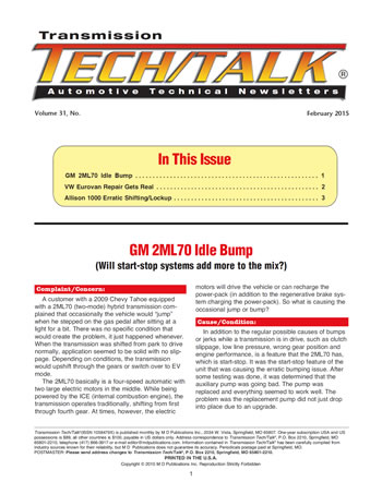
One way to over-come the problem is to maintain line pressure by some means other than the main pump. In the case of the 2ML70, an auxiliary pump was added to the transmission housing. When the engine stops, the auxiliary pump kicks on to maintain internal clutch apply pressure, (Figure 1). The auxiliary pump system has its own filter, test plug and pressure-regulator valve. The pump is controlled by a separate module, which also can cause problems. This approach is gaining usage, with more transmission types being outfitted with auxiliary pumps for the start-stop systems.
Another approach to maintaining pressure with the engine off was developed by ZF. It is an accumulator system comprised of a spring-loaded cylinder that gets charged with the engine running and supplies pressure when the engine shuts off.
Regardless of the method, start-stop is here to stay. Although the Tahoe did not display any trouble codes, there are codes that can be set. To start with, if the DTC (Diagnostic Trouble Code) P079A was set, it would indicate a slipping low 1-2 clutch assembly which could cause a bump. A P0C2B would refer to an auxiliary pump feedback circuit issue, while a P2797 code would indicate a pump performance issue.
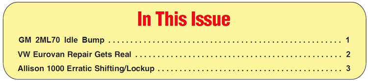
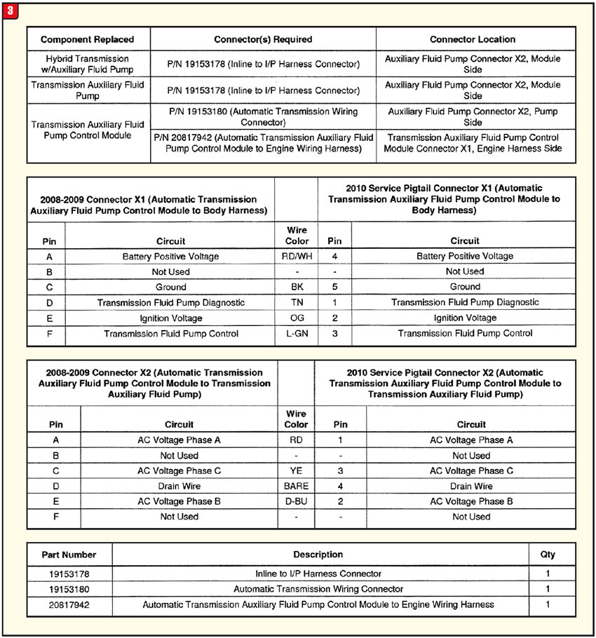
Fortunately, replacing the auxiliary pump on a 2ML70 is not difficult since it bolts on externally, (Figure 2). The problem with a 2008 or 09 model is that the auxiliary pump and control module have been upgraded due to the connectors. The part numbers of the pumps are 19168291 (2008-09) and 19207983 (2010-Up). The auxiliary pump control-module part number is 29546636 and it fits only 2010-Up.
Flip-flopping the two components requires specific harness connectors, depending upon the direction. The accompanying four charts illustrate the part numbers and positions involved, (Figure 3). Beyond traditional transmission issues, the additional components used in start-stop will provide more opportunities (or problems, depending on your view). Time will tell.


A 2002 Volkswagen Eurovan came in with noise and shift issues. The vehicle had a 01P transmission, which is the lockup version of the AG4 family. Since the van had 110,000 miles on it and the drivability symptoms, we dropped the pan to check for damage. We found a fair amount of debris, so the unit was pulled out and disassembled. Basically, the K1 clutch was trashed and the B2 brake had signs of slippage, so the transmission was completely rebuilt and reinstalled. The road test went well and the vehicle was delivered, only to return a week later.
Upon his return, the customer reported that one day he put the transmission in drive and heard a noise similar to the original noise. Beyond that, he noticed some wet spots under the vehicle where it was parked in the garage.
The van was taken for another road test and, sure enough, the transmission made a rubbing noise going into drive. Everything else seemed okay and the vehicle was put on a lift to check for leaks. There was a leak, but instead of transmission fluid, the liquid appeared to be antifreeze.
We decided to pull the transmission due to the noise problem, but just as the transmission was ready to drop, things got ugly. When the top bell-housing bolt was removed, a stream of antifreeze poured out (which is rather uncommon).
At that point, repairing the transmission became a distant second in the priority pecking order. Visions of replacing an engine passed through everyoneʼs minds, but then came the question, “How did this happen?”
Not only is the transmission installed into the Eurovan with a shoe horn (itʼs really tight), but the transmission-to-engine bolt selection was developed by the same engineers responsible for Honda valve-body bolts. There are a lot of them.
The bell housing bolt arrangement is inconsistent, however, the hole in question is at the top of the engine and is a blind hole at the edge of a water jacket (Figure 4).
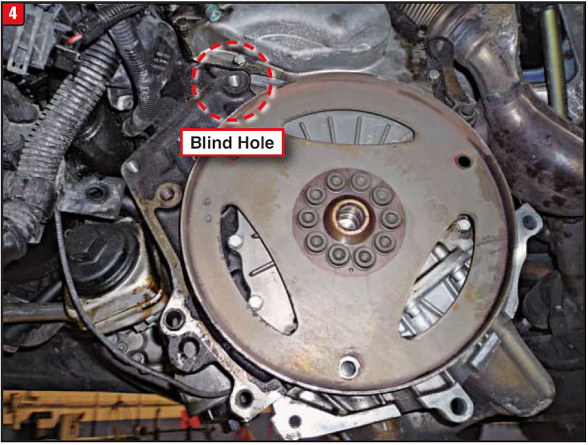
When the installer removed the unit initially, he did not pay close enough attention to the various lengths of bolts (which are several). In addition to the varying lengths, a few of the bolts are pointed, for some reason (Figure 5).
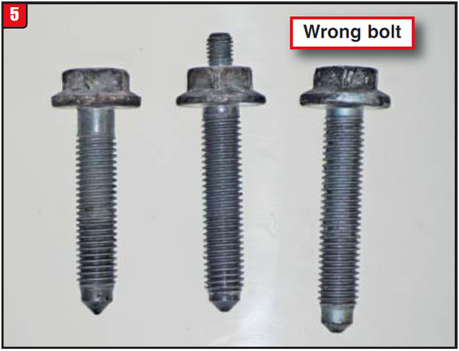
Unfortunately, the installer put the longest bolt with the sharpest point into the hole right next to the water jacket and punched a hole into it. It took time for the antifreeze to wick through the bolt threads and leak out.
To address the crack in the engine bolt hole, a piece of bolt was cut (approx. ¼” long) and slotted for a screwdriver. The hole was cleaned out and an epoxy was applied to the threads in the hole and the short piece of bolt. The piece was inserted and the epoxy was allowed to dry. Engine coolant then was added to check for leaks. It worked and there were sufficient threads remaining for a bell-housing bolt. Crisis averted!
Now that we solved the antifreeze leak, we were back to the original noise complaint. The transmission pump was pulled and clutch drums were removed to find the source of the noise, which was caused by the K1 clutch hub floating rearward, allowing the bottom friction plate to drop off the end of the hub. Noise would then occur during neutral/drive apply. How could this happen?
AG4 transmissions have a unique K1 clutch and K1 hub arrangement. Unlike normal clutch hubs that are held in place by thrust washers or bearings, the AG4 (01P) hub is held in place by the tabs of the four plastic inserts that act as a bushing between the hub and K3 drum. Somehow, these tabs broke off and allowed the hub to float.
When assembling the K1 clutch, load some of the frictions, steels and the backing onto the K1 hub, then insert the plastic guides. Place the rest of the plates into the K1 drum and then set the hub and installed plates into the drum along with the snap-ring to ensure the correct position. Use caution when pressing in the K3 drum to avoid breaking the inserts.
Two fixes for the price of one. Always check bolt designs to avoid additional grief.


A 2005 Chevy Silverado 2500 pickup was experiencing inconsistent upshifts and at times would trigger a Check Engine light. In addition to the shifting issue, torque converter lockup would not apply.
We attached a scanner and pulled the diagnostic trouble codes, which were P0716 and P0735, indicating an issue with the ISS (Input Speed Sensor). After the codes were erased, the truck was driven again and it worked well – at least for a bit – but trouble codes would reset and apply issues would occur when the vehicle was cold. When we allowed the vehicle to warm up and everything worked normally.
The customer reported that the Check Engine light had appeared before on occasion and that he had taken the truck to another repair facility. Things started to get worse after that visit. For whatever reason, the other shop did replace the transmission ISS, but to no avail.
We test-drove the vehicle again with a scanner hooked up to read ISS output. Initially, the ISS reading was within spec; however, once freeze-frame was used a glitch did appear, indicating a faulty ISS. The ISS had been replaced already, so the question became, “What related issue could there be causing the problem?”
We checked the wiring harness and electrical connector at the ISS and it appeared to be in good shape. The next step was to remove the ISS and try another one; however, as soon as the ISS was pulled, the observant technician saw the problem: It was “crud”.
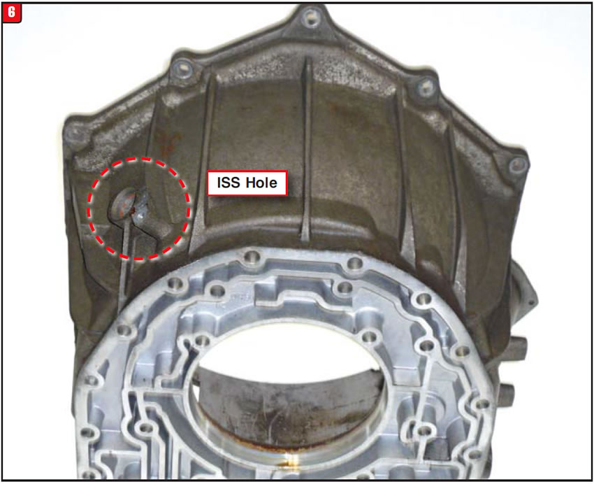
The Allison 1000 series uses three RPM sensors: ISS, TSS (Turbine-Shaft Speed Sensor and OSS (Output Speed Sensor). The ISS is located on the bell housing 6 (Figure 6). The bell housing for the Allison 1000 is no small piece of aluminum, but contains many of the worm tracks that connect to the pump cover. The ISS sticks through a hole in the upper part of the bell and the probe reads the impeller dimples of the torque converter.
As with any RPM sensor, the air gap (the space between the probe and sensor contact) must be correct. If the gap is excessive there is no sensor output.
Worse yet, if the gap is inconsistent, such as a small dent in the converter impeller, the erratic conditions make diagnosis that much harder. In the case of this Silverado, the torque converter was not the issue, but rather it was the hole in the bell housing (Figure 7). Whatever prompted the first shop to replace the ISS was made worse due to the rust build-up at the surface of the hole as Figure 7 illustrates.
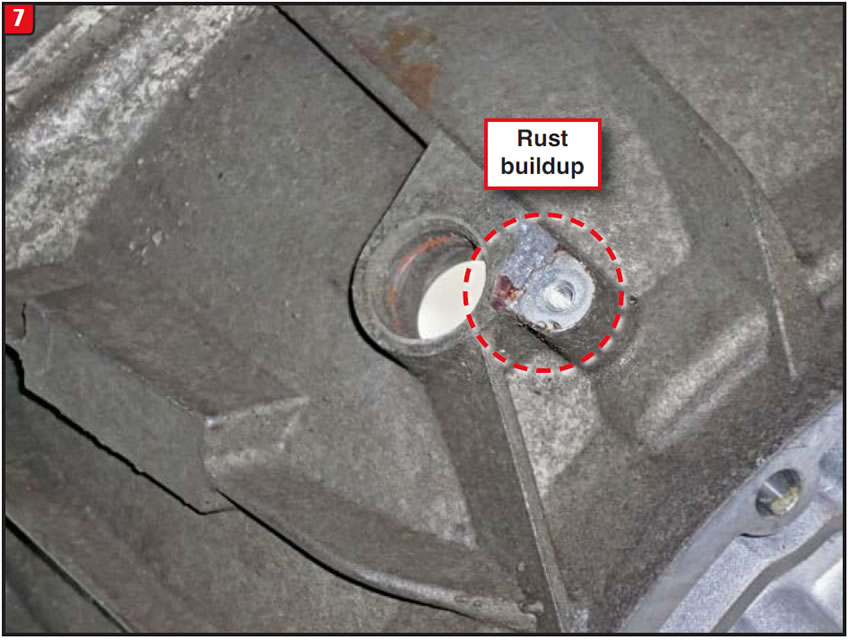
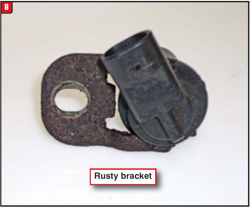
When the first shop removed the original ISS from the bell housing, rust from the old ISS hold-down bracket transferred to the bell. After a period of time, excessive rust and corrosion can build up on the bracket (Figure 8).
Verifying correct sensor air gap may be difficult in some cases but should be done nevertheless. Beyond the normal variables that could exist (such as surface irregularities) there are design changes in sensors or reluctor/sensor rings to consider.
Transmissions such as the CD4E or 4R70W have had component changes and part mismatches can affect air gap. At least the three Allison 1000 RPM sensors are the same, part #29536408.
Although there were two different diagnostic trouble codes set, the P0716 and P0735 codes may not tell the entire story as they did on the Silverado. Look beyond scanner info and always be aware of the gaps.
Special thanks to Jim Gillece at Gillece Transmission in Pittsburgh, PA.

February 2015 Issue
Volume 31, No.
- GM 2ML70 Idle Bump
- VW Eurovan Repair Gets Real
- Allison 1000 Erratic Shifting/Lockup


