

Issue Summary:
- On a GM vehicle with the 4T65-E automatic transaxle, OBD-II service code P0742, “TCC Stuck On,” can be caused by a sticking TCC release switch on the pressure-switch manifold, a clogged TCC PWM solenoid or a short to ground of the TCC release-switch wire.
- A squealing noise from the bellhousing and converter area of a Ford Escort with the F4EAT transaxle can be caused by a clogged pollution-control valve.


Before or after overhaul, a vehicle equipped with the 4T65-E automatic transaxle logs OBD-II service code P0742, “TCC Stuck On.” When this code is set in the computer, the powertrain control module will command the torqueconverter clutch on at full capacity and freeze shift adapts.

This condition may be caused mechanically by a sticking TCC release switch on the pressure-switch manifold, or hydraulically by a clogged TCC pulse-width-modulated solenoid. Note: Installing a TCC PWM solenoid from a 4L60-E on this vehicle will cause the same reaction as a clogged solenoid.
This problem also may be caused electrically by a short to ground of the TCC release-switch wire.

To correct this problem, you first must establish whether the trouble is mechanical, hydraulic or electrical in nature.
Hook up a scan tool and locate the parameter for TCC release. The TCC release switch in the pressure-switch manifold is a normally closed switch; the switch is held open by the presence of TCC release pressure at the switch (refer to Figure 1 for description and operation of the pressure-switch manifold). With the scan tool connected and the vehicle started in Park, the indication on the scan tool should show the switch to be open. Depending on the scan tool, the indication shown may be either “0 open” or “1 closed,” “P2 open” or “P1 closed,” or simply “High open” or “Low closed” (refer to Figure 2 for the pressure-switch-manifold readings on the scan tool).
If the scan tool shows the switch to be closed, the trouble will be caused by either a stuck TCC release switch or a short to ground on the signal wire from the TCC release switch to the computer.
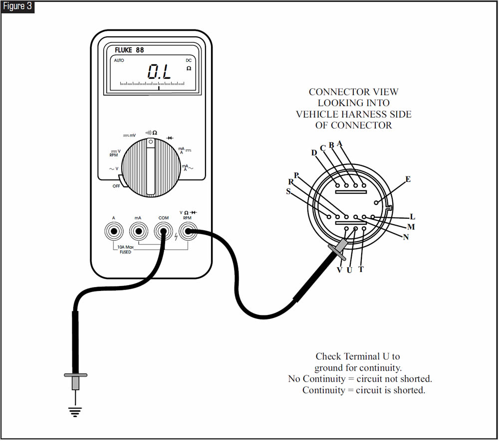
Go to Correction 1: Electrical/Mechanical and refer to Figure 3 to check for a shorted wire in the TCC release-switch circuit. Refer to Figure 4 to check for a stuck TCC release switch.
Go to Correction 2: Hydraulic and refer to figures 5-7 for TCC PWM hydraulic-circuit description.
Correction 1: Electrical/Mechanical
If the indication on the scan tool shows the switch to be open, hold the brake and place the selector lever in the Drive position. Allow the wheels to spin and watch the scan tool as the vehicle upshifts to second gear. If the indication on the scan tool changes from open to closed with the shift into second gear, check the parameter for TCC duty cycle and see what the reading shows. A reading of 0% duty cycle would indicate that the computer has not commanded lockup. If the computer has not commanded lockup, but TCC release oil has exhausted (noted by the change in state of the TCC release switch on the scan tool), this could indicate a clogged TCC PWM solenoid.
The pressure-switch manifold on the valve body of the 4T65-E transaxle is a switch assembly containing six fluid-pressure switches. Three of these pressure switches – D4, LO and REV – are normally open switches, and the other three – D3, D2 and TCC release – are normally closed switches. The PCM uses these switches, with the exception of the TCC release switch, to determine the position of the manual valve in the transmission. The PCM uses the TCC release switch as a diagnostic aid to confirm the ON/OFF status of the TCC during operation of the vehicle.
Figure 1 shows the fluid-pressure status at each of the six switches in the pressure-switch manifold with the engine running and the selector in each quadrant position. The 0 indicates no pressure at the switch in the chosen selector range, and a 1 indicates pressure is present.
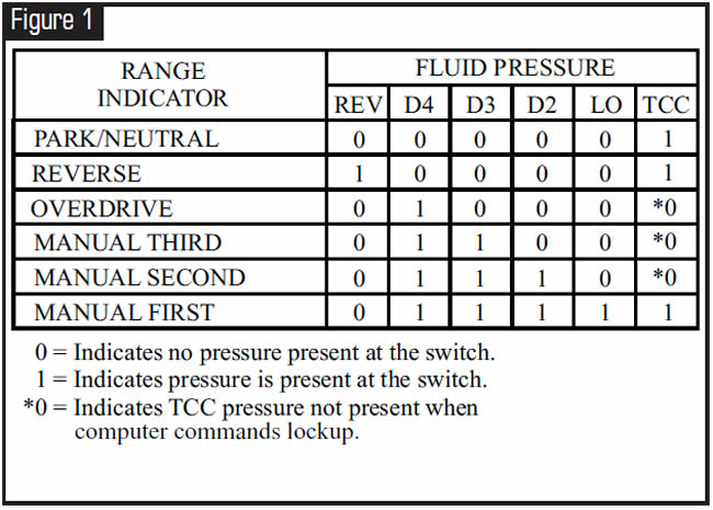
Figure 2 illustrates the indications shown on a scan tool as the range parameters E, D, C and TCC release are being checked. “High” indicates the switch is open, and “Low” indicates the switch is closed as you view the data stream on the scan tool.
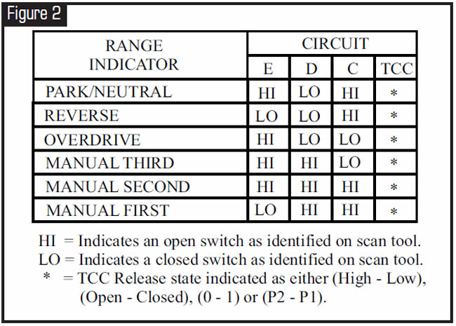
Note: When you’re viewing the parameter for TCC release, the indication on the scan tool may be “0 open” or “1 closed,” “P2 open” or “P1 closed,” or simply “High open” or “Low closed,” depending on the scan tool.
If the meter does indicate an open circuit when you check the case connector, the wire is not shorted to ground and a check of the TCC release switch on the pressure-switch manifold will be necessary (refer to Figure 4 for information on checking the pressure-switch manifold).
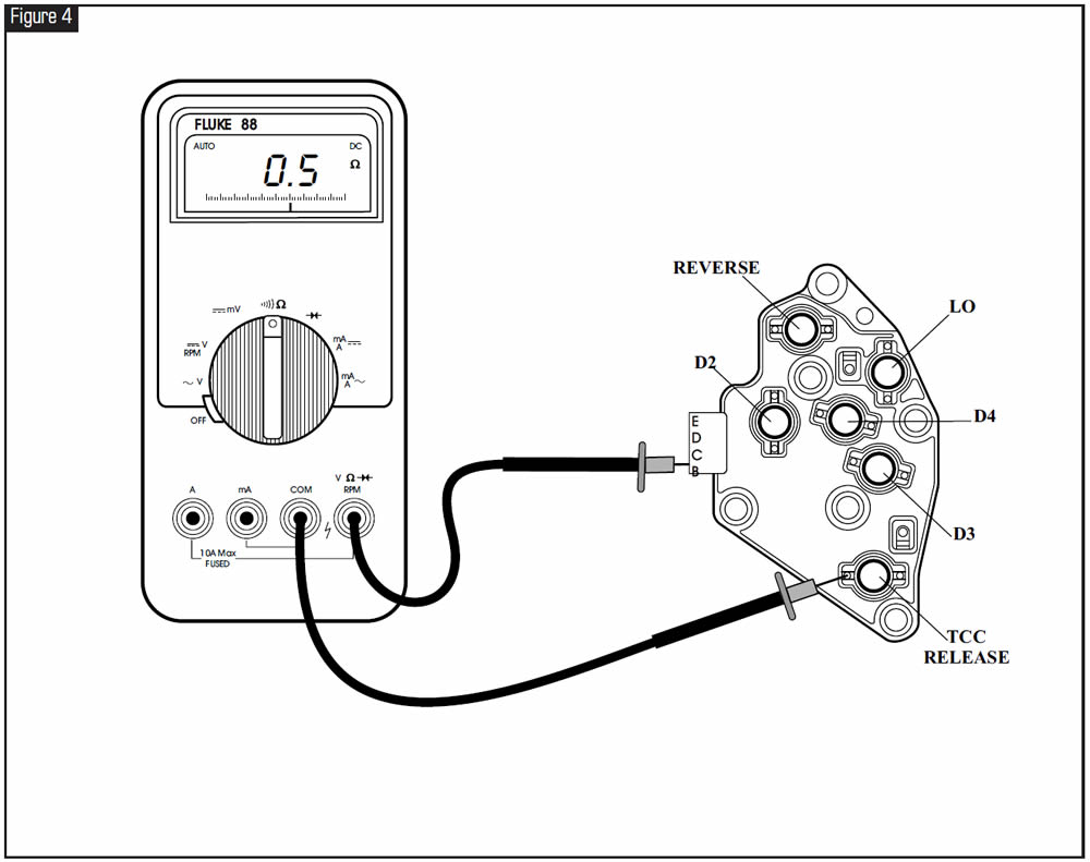
Unbolt and remove the switch from the transmission, and place the switch on a work bench. Using the DVOM, set the meter to check for continuity or resistance, place the positive lead of the meter on terminal B at the connector and place the negative lead of the meter on the metal contact of the TCC release switch. The meter should indicate continuity, or about 0.5 ohm. Press down firmly on the switch contact where the O-ring is, then check the meter. The meter should indicate no continuity, or an open circuit. If the meter doesn’t indicate an open circuit after you press the switch contact, replace the pressure-switch manifold.
Correction 2: Hydraulic
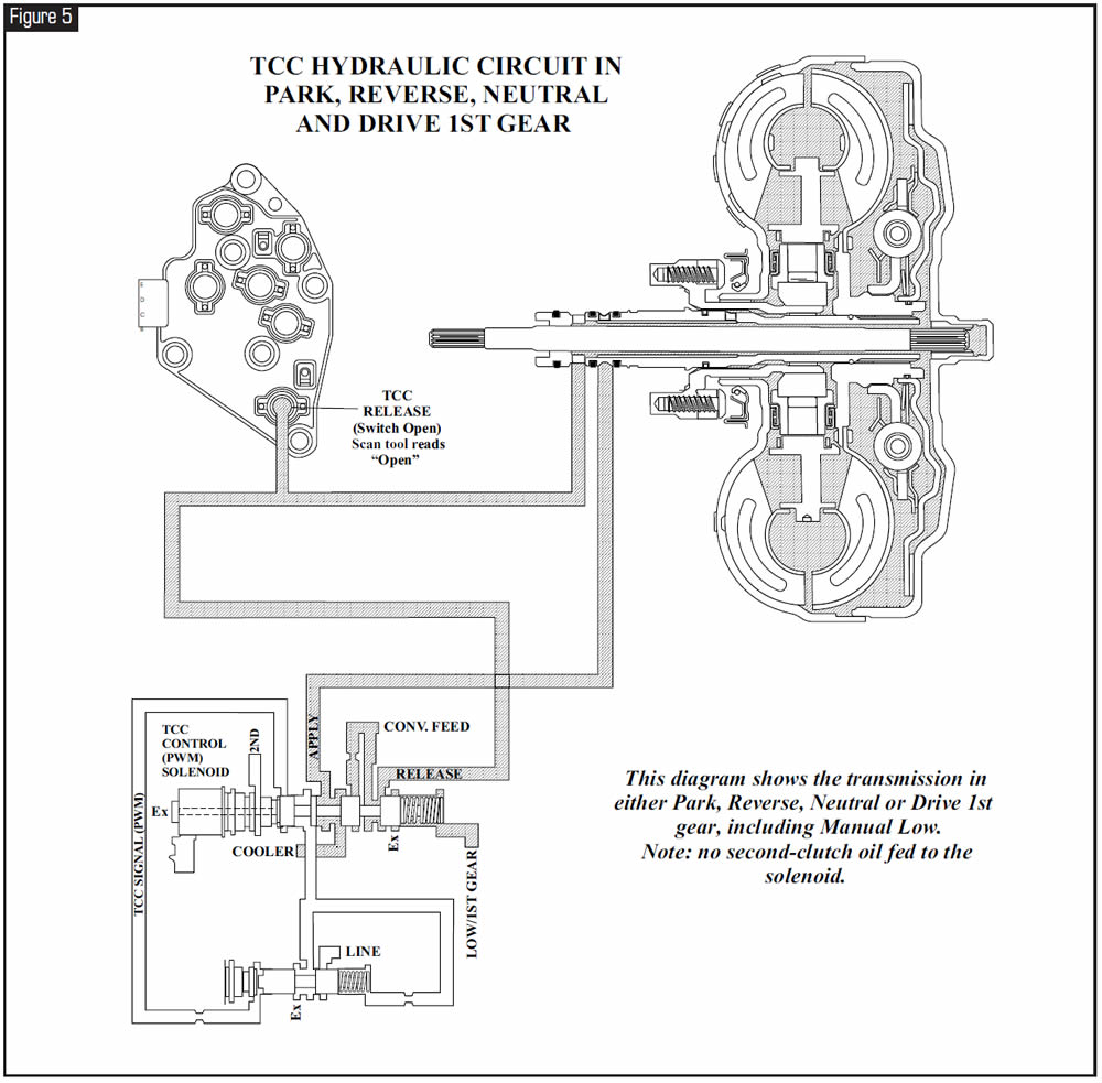
The hydraulic diagram shown in Figure 5 represents the transmission in either Park, Reverse, Neutral or Drive 1st gear, including manual Low. When you look at the feed from second gear to the TCC PWM solenoid, you will notice the lack of oil pressure in the circuit. This is because oil pressure is present only when the second clutch is applied (which would be second, third and fourth gears on this transmission). With no oil pressure at the second clutch, the TCC control valve stays at rest in its bore away from the spring. This results in oil pressure being present at the TCC release switch in the pressure-switch manifold, keeping the release switch open.
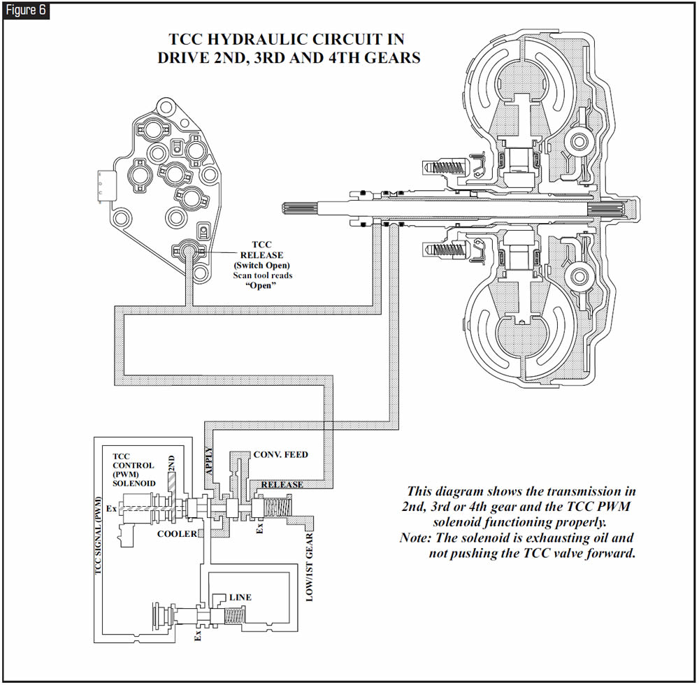
The hydraulic diagram in Figure 6 represents the transmission in Drive 2nd, 3rd and 4th gears. Notice the presence of 2nd-gear oil pressure in the circuit. With the solenoid “OFF” and not energized, the solenoid should exhaust 2nd-clutch pressure so that the pressure in the solenoid doesn’t become great enough to cause the TCC valve to stroke inward against the spring. Lockup will not be engaged at this time.
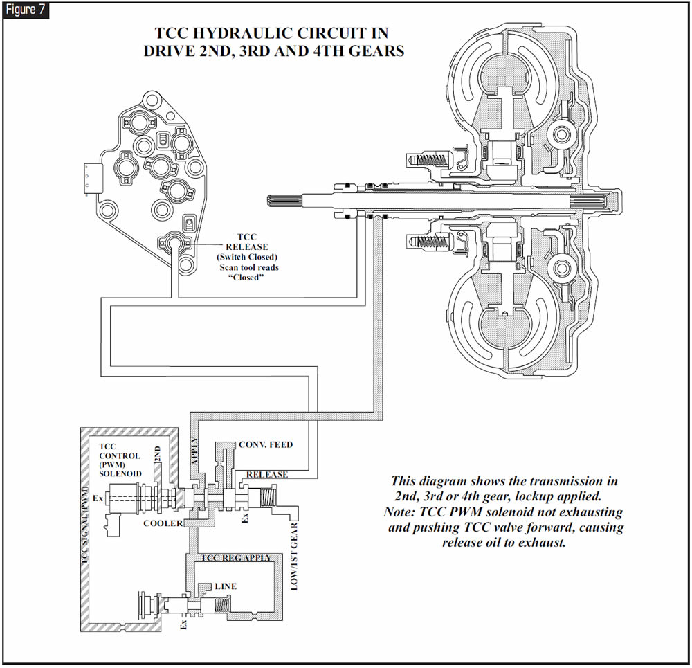
The hydraulic diagram in Figure 7 also represents the transmission in Drive 2nd, 3rd and 4th gears, with the lockup clutch applied. If for some reason the TCC solenoid is not capable of exhausting 2nd-clutch oil pressure, the TCC control valve will overcome spring tension and move into the lockup position. Lockup release oil will exhaust through the valve, and the converter clutch will engage with the shift into second gear. Replacing the TCC PWM solenoid should correct the problem.
There have been instances of a new factory TCC PWM solenoid for the 4L60-E being used in the 4T65-E. Even though the solenoids for these two units look identical, they will not interchange; use only the TCC PWM solenoid for a 4T65-E.

- TCC PWM Solenoid, Part # 24214974.


A Ford Escort with the F4EAT transaxle exhibits a squealing-type noise that is coming from the bell-housing and converter area. The first impression is a torque-converter problem. However, replacing the converter doesn’t make the noise go away.
This condition may be caused by a clogged PCV pollution-control valve. If the valve won’t allow air to be drawn through it, engine vacuum may become strong enough to pull in air through the rear-main engine seal. If this occurs, a high-pitched squealing noise may result from the vibration of the seal against the crankshaft as air is pulled through the seal into the engine (see Figure 8). Disconnect the PCV valve as shown in Figure 8 to verify that it is the problem. The squealing should stop immediately.
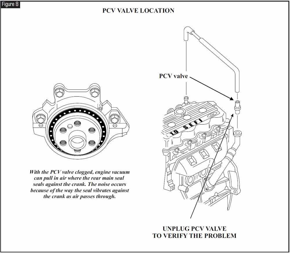
Replacing the PCV valve will correct this problem. See Figure 8.


February 2004 Issue
Volume 21, No. 2
- GM 4T65-E: DTC P0742 – TCC Stuck On
- Ford Escort: Squealing Noise


