Tech to Tech
- Subject: Throttle-position-sensor code
- Vehicle Application: 2004 Ford F-150 pickup
- Essential Reading: Diagnostician
- Author: Jeff Bach
Troubleshooting a TPS shows that either the voltage or programming is the culprit
When it comes to on-the-job training, automotive repair has to be – in my opinion – one of the top schools. Much time is spent wading through the myriad of technical info, Web-site access to programs and update downloads. Just having the right tools necessary to get the proper data from the right computers is challenging enough. When you throw wrong parts into the mix, problems just compound.
Many of the components on modern automobiles are scrutinized tightly by the powertrain control module (PCM) to determine their viability in the chain of controls necessary to maintain emission standards set by the Environmental Protection Agency. These tight standards include comprehensive component testing that must be done by onboard controls. Each manufacturer has its own idea for component testing and problem reporting.
Seemingly subtle variances in signals from sensors can trigger major changes in fuel and emission controls. Such was the case in my most-recent adventure into solving a drivability problem for a friend who owns a shop across town from me. This fellow doesn’t give up on problem jobs and sends cars to the dealer only for absolutely necessary things such as programming of computers. When we discussed the problem he was having with this 2004 Ford F-150 5.4 engine, it sounded like a problem that wouldn’t be too difficult to resolve.
He had done all the things required of him, according to the trouble-tree chart for the codes and symptoms he was having. The next step in the charts was installing and programming a new PCM. He asked me what he needed to buy to do this himself without having to send the vehicle to the dealer. I informed him that he should be able to get this accomplished with a J2534 interface and buying a programming subscription from Motorcraft. He decided that, in the interest of time, he would let us program this one and he would look into getting himself equipped later.
When I got the truck here, I test drove it with my scan tool connected and got the P0121 throttle-position-sensor (TPS) code, along with the P2106 that my friend was trying to get resolved. The truck was missing badly. It felt like the ignition was breaking down on at least two cylinders. I proceeded to reflash the PCM, using the Ford flash programming software that I downloaded from the Motorcraft service Web site.

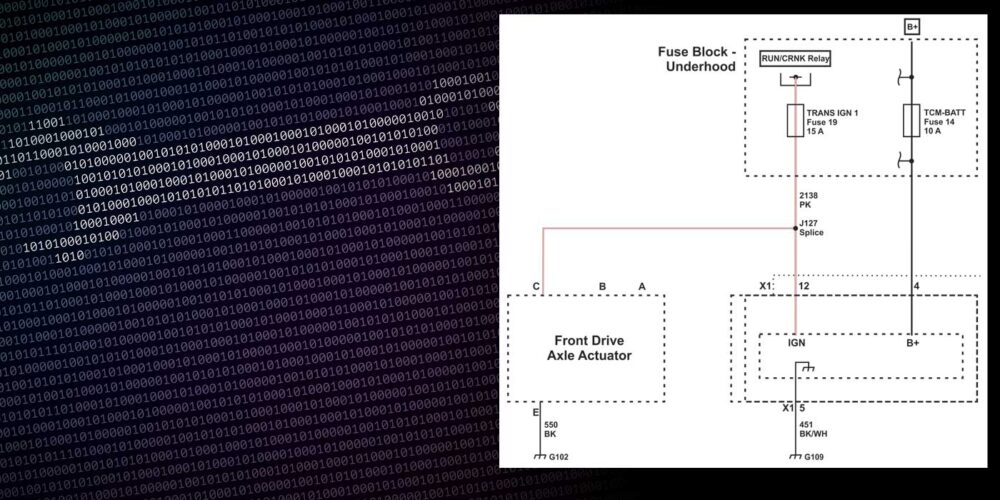
Unfortunately, it didn’t help to resolve the drivability issue, and the truck was still setting the same codes. I decided to get a scope reading from the TPS to see what the PCM was seeing. I used the two signal wires, which run opposite each other for redundancy, due to the fact that it’s a drive-by-wire system. This system uses a throttle-pedal-position sensor that sends three signals to the PCM based on driver pedal input. This in turn controls the throttle plate, using a two-wire throttle actuator control (TAC) reversible motor monitored by the throttle-actuator-control throttle-position sensor (TACTPS) that uses two reference signals, a ground and two sensor inputs to the PCM. Figure 1 shows the waves I received from the TACTPS.
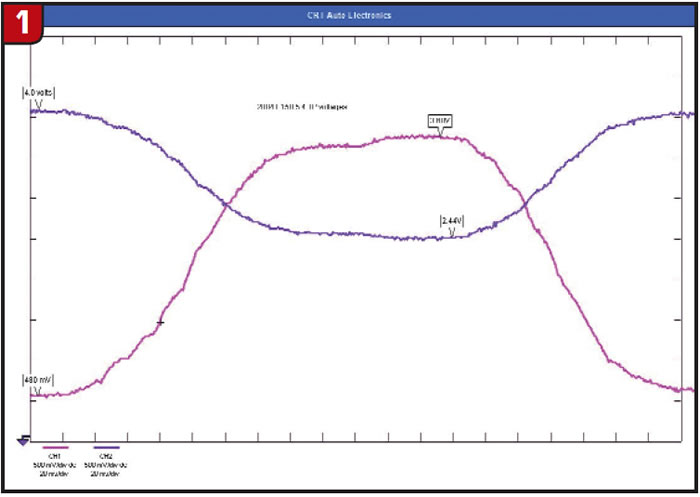
Nothing stood out as a glaring glitch in this first set of waveforms, but there does seem to be a rather lumpy “non-linear” response to the throttle input. The code set as soon as a key-on, engine-running (KOER) test was performed before the PCM could see a sweep of the sensor signals. The voltages were well within the range of voltages shown in the trouble tree, and this was the third sensor the truck had seen. The chart showed a Type 1 and a Type 2 TACTPS, with the resistance being different by almost 20%.
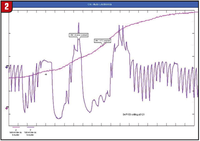
I checked the number on the TPS and called the dealer to see whether it crossed to the right one for the VIN on the truck. The dealer said that the TPS number I gave him didn’t even cross to a truck. My friend assured me that he had put the right TPS on because he got it from the dealer and he used the truck’s VIN to make sure it was right. I double-checked with my dealer, then I ordered the right TACTPS and installed it, expecting to see some improvement. I cleared the codes and did another KOER test, with the same codes still coming up. I decided to take a look at the TAC motor current with my current probe just the same, since I needed one for my waveform collection. Figure 2 is what I came up with using throttle-actuator-control throttle-position sensor 2 (TACTP2) and the TAC motor current.
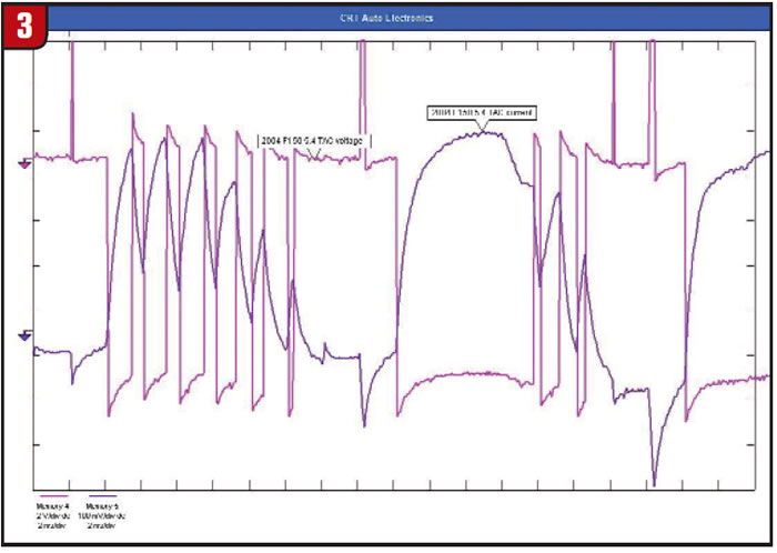
Not exactly the prettiest current-control signal I’ve seen but not necessarily bad enough to make a call on the PCM. I have seen similar TAC control current on late-model GM cars. My next thought was, “Does the TAC motor have, say, a brush-contact issue or was it a brushless motor?” I figured it would be advantageous to see the voltage control circuit and the current at the same time. Figure 3 was the result of that sweep test.
Following the trouble chart leads to replacing the PCM, and from the way this looks, I’d say the PCM was having a problem with the TAC driver circuit. I wanted to see whether there was a difference in the “right” TPS from the one I had the signals for previously, so I collected some more waveforms and stacked the old ones on the new one for comparison. Figure 4 shows the achieved results.

Seeing the difference in the TPS voltages, I decided it might be worth a shot at reprogramming the PCM again with the right TPS installed. This time, when I linked up to the Web-site reprogramming tool, I got a message stating that the flash I was about to install covered a bulletin fix that might be covered under warranty and that I needed to agree to print out a statement and have the customer sign it, stating they knew that if the flash were done by someone other than the dealer, they could not get reimbursed for it. I agreed.
I reprogrammed the PCM and the light went out; the codes were gone; the running condition disappeared. Wondering how much change was made in the way the PCM controlled the TAC motor, I took another shot of the TAC current and voltage signals. Figure 5 shows the stack of the “before and after” of the two signals.
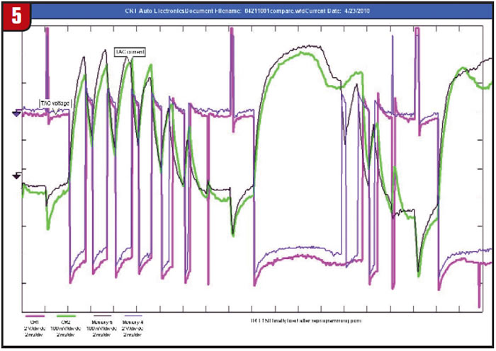
The signals in the bolder lines are from the TAC motor current and voltage after the vehicle was repaired. These signals were both taken at the start of a throttle sweep and looked amazingly similar.
Since the codes are gone and the thing runs great now, I will assume it was either the slight difference in the TPS voltages or else there was a change in the PCM programming that came about in the two days that I had the vehicle. Either way, it ended up being one of those time-burning jobs that you have to “chalk up to experience.” The funny thing is that once I explained what all we found and showed my friend the waveforms we captured, his response was, “I’ll just keep sending this kind to you.”
Jeff Bach is the owner of CRT Auto Electronics, an ASA-member shop in Batavia, Ohio. For more information on this topic, contact Bach at (515) 732-3965. His e-mail address is [email protected].
This copyrighted article is reprinted with the permission of AutoInc., the official publication of the Automotive Service Association (ASA). To learn more about ASA and its commitment to independent automotive-service and repair professionals, visit www.ASAshop.org or call 800-272-7467.