
Technically Speaking
- Author: Wayne Colonna, Technical Editor
I believe it is “safe” to say that the 41TE (A604) was the first to have a “limp-in mode” (also referred to as “failsafe”) in which the strategy of the transmission control module (TCM) was to place the transaxle into a specific gear (2nd) after it detected a fault. The E4OD transmissions were on the road at that time, and Ford’s strategy was to elevate line pressure (FMEM – Failure Mode Effect Management) rather than placing the transmission into one specific gear.
Since then, technology has leaped forward at a vicious pace, not breaking for breath. And with this technological race among the “Big 3” manufacturers (U.S., Japan and Europe) comes the need for various computer strategies. Failsafe is one of those strategies that has experienced a change.
For example, in the August 2002 issue of Transmission Digest I wrote an article called “Howzetwerks” pertaining to the Mercedes 722.6 transmission. In that article I presented the shift sequence of the solenoids through an ON/OFF application chart, as you can see in this article in Figure 1. Shift solenoids 1-2/4-5, 2-3 and 3-4 are toggled off- on-off in making their respective shifts. While the transmission is in gear they remain in the off state. This type of strategy allows the computer to failsafe the transmission in whichever gear it was in at the time the computer system observed a fault. Not until after the vehicle is brought to a stop and the ignition is cycled will the transmission default to second gear (using the equivalent transmission with the W5A 580 designation, this strategy remains the same in Jaguar’s V-8 XJ8 and XK8 models).

Another manufacturer that incorporates a slight twist in its failsafe strategy is ZF Industries in its ZF-4HP-18 FLE and FLA transmissions (see Figure 2). Vehicles in the United States that would have this style of transmission are 1991-97 Audi 100 Quatro and A6, 1994-96 Audi A8 and 1991-94 Porsches.
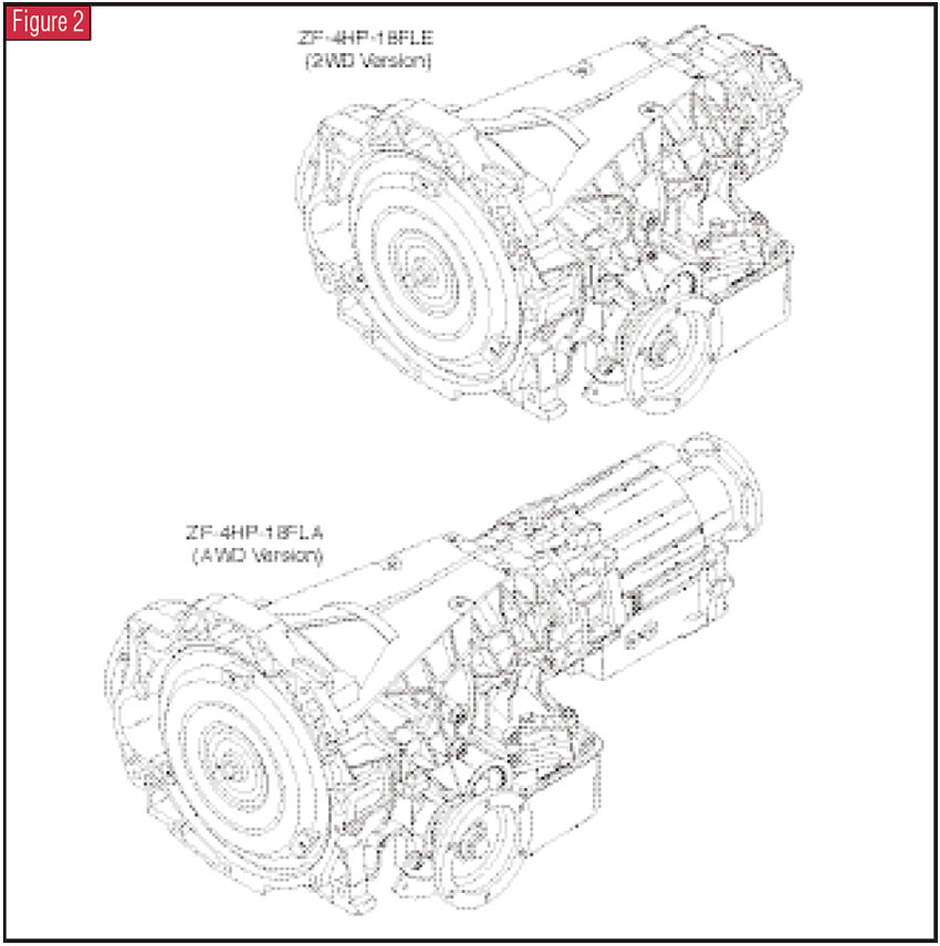
Before we enter the explanation of this failsafe strategy, it is important to note that this particular unit has a 3-4 clutch called the E clutch that is driven through the damper plate in the converter similar to that of a Ford AOD or VW/Audi’s Phase 0 and 1 transmissions. This means that there is no converter-clutch operation and that 3rd and 4th gears basically are driven off the crankshaft. This piece of information will enter into the failsafe strategy in just a little while.
Figure 3 illustrates both a clutch and solenoid application chart. A careful observation of this chart reveals that the MV1 and MV3 solenoids are the two shift solenoids that shift this transmission through its four gears. You also can see that both these solenoids are off for 4th gear and for 2nd-gear failsafe. So the question arises: How can all the solenoids be off to make 4th gear yet also all be off to make 2nd-gear failsafe? This task is achieved via the MV2 solenoid, the pump and the safety-mode valve.
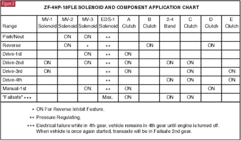
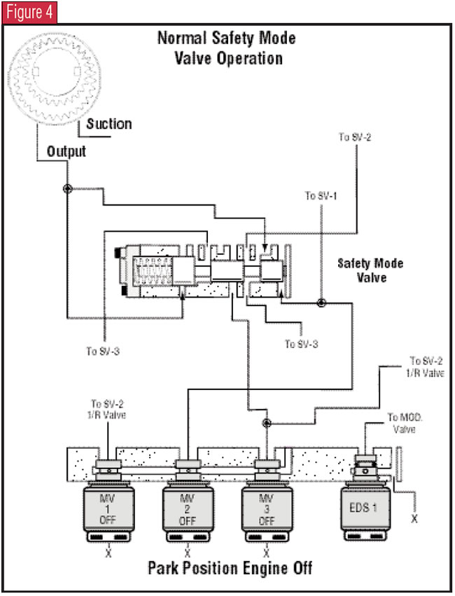
Figure 4 provides a partial hydraulic diagram in the Park position with the engine off. Without hydraulic pressure and with all solenoids off, the spring is holding the safety-mode valve to the right. If you look carefully, you will see that pump pressure is routed to and blocked by the land of the safety-mode valve closest to the spring. You will notice that pump pressure is routed to the right side of the valve as well. But when the ignition is cycled, the MV2 solenoid turns on. As soon as the engine starts and there is pressure in the system, MV2 solenoid oil strokes the safety-mode valve to the left. Once the valve is stroked, the pump pressure routed to the left side of the valve holds it to the left and the pump pressure on the right side of the valve is blocked.
And that is exactly what Figure 5 illustrates with the vehicle started in Park. With the safety-mode valve now stroked to the left, it becomes a gateway for the MV3 solenoid oil to act on shift valves (SV) 2 and 3.
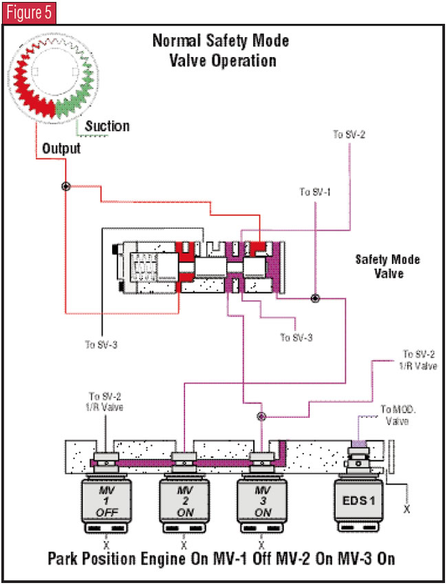
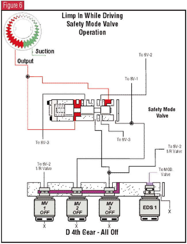
In short, with the safety-mode valve stroked to the left, the MV1 and MV3 solenoids can work together, directing oil to the appropriate band or clutches. When both solenoids are turned off and the safety-mode valve is held to the left by pump pressure, both shift valves 2 and 3 are held closed by spring tension and fourth gear is achieved (see Figure 6).
Now, if the computer system detects a fault while the vehicle is being driven, it can shut the solenoids off and the vehicle will be in fourth gear. But it cannot come to a stop in fourth gear. If you remember from just a few paragraphs ago, 3rd and 4th gears basically are driven off the crankshaft via the E clutch through the damper plate in the converter. Coming to a stop in fourth gear would stall the engine. So the transmission can failsafe to fourth while the vehicle is being driven, but when it comes to a stop, the computer will command second gear electronically by energizing both shift solenoids, which strokes both shift valves. This action will prevent a stall from occurring.
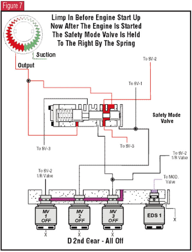
Figure 7 illustrates what happens now when the vehicle is turned off and pump pressure stops. The safety-mode valve is forced to the right by spring tension. When the vehicle is started, the computer will not cycle any of the solenoids, especially the MV2. Without stroking the safety-mode valve, the pump pressure going to the right end of the valve is able to be directed to and stroke both shift valves, placing the vehicle in 2nd-gear failsafe with both solenoids off.
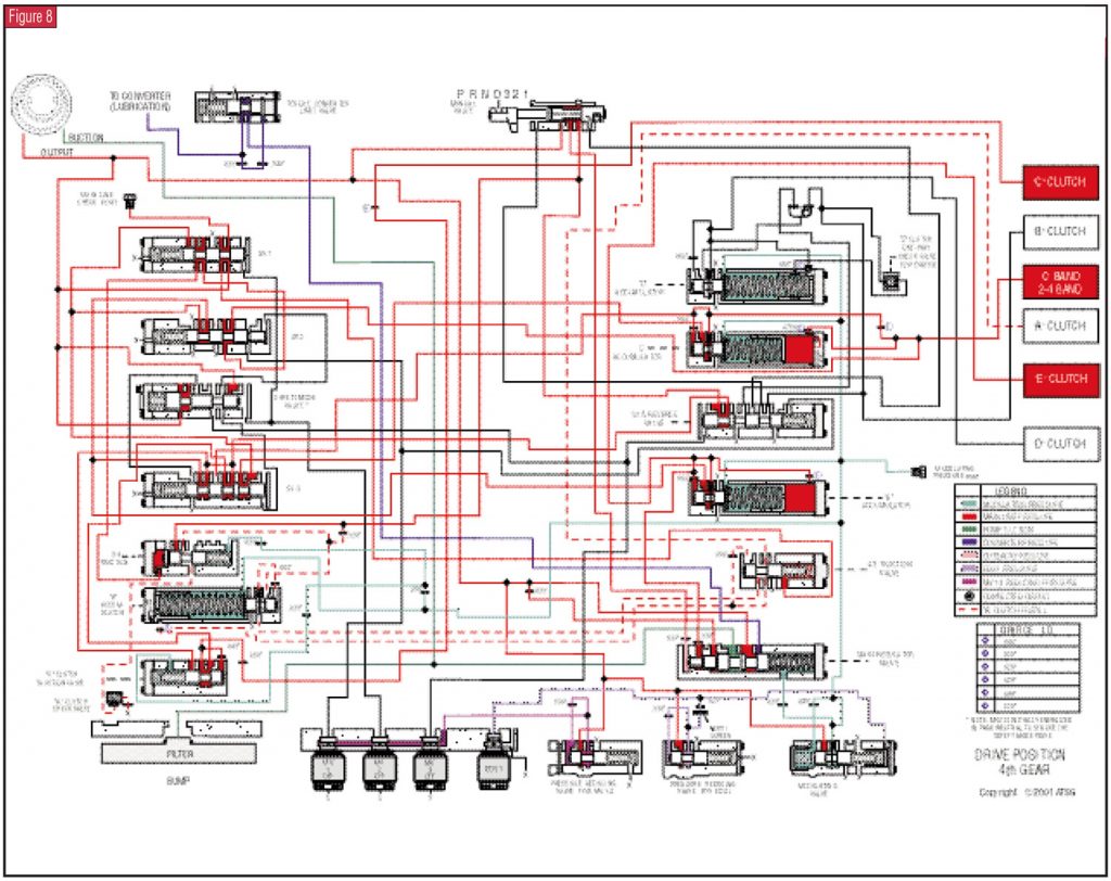
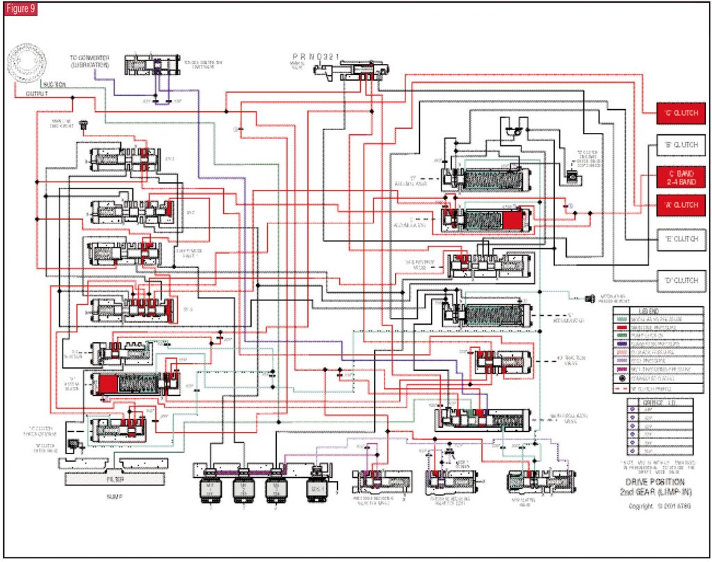
Now that you have this understanding, illustrated in Figure 8 is a full hydraulic schematic of both solenoids off in fourth gear. Figure 9 shows both solenoids off in 2nd-gear failsafe. You can use these two figures for comparison.
This concept of the safety-mode valve with ZF is not unique. The new 5L40-E transmission in some late-model 3 and 5 Series BMWs and Cadillac’s CTS vehicles employs a similar strategy in that it too uses a safety-mode valve to determine different failsafe modes. During driving conditions it will failsafe to 5th gear, but after an ignition cycle, it will be in failsafe 4th gear.
Admittedly, though, the ZF strategy is a bit more involved because of the direct link from the crankshaft into the transmission when the vehicle is in third or fourth gear. This type of configuration adds another dimension to the computer’s failsafe shift strategy. It also means that if loss of power to the solenoids occurred while you were driving a vehicle with one of these ZFs, it would dump to fourth and when you came to a stop would stay in fourth and stall the engine. If you didn’t know this unit’s operation, it would be reasonable to think that failure of the converter-clutch solenoid was the problem. How surprising it would be when you tried to order one and learned that it does not exist!

Many thanks to Jim Dial for all the ZF illustrations used in this article! Full, complete oil schematics and valve-body mapping for this ZF transmission and VW/Audi 01M transmission are available in ATSG’s online bookstore at www.atsgmiami.com.


