An easier way to install the center support in GM transmissions - Transmission Digest

An easier way to install the center support in GM transmissions

Whether you are working on a 6L45, 50, 80 or 90, installing the center support that houses the L/R and 2-6 Brake clutches into the case can at times be difficult. In the past, I would grab the inside of the assembly with my fingertips on the friction teeth of the 2-6 clutch pack. I’d lift it up and bring it down into the case as perfectly as I could so it wouldn’t get cocked in the case. And if all went well, the L/R clutch would index and the assembly would slide right in. But then there were times when it needed to be jiggled around before it finally sat in place. By this time, I would have raw fingertips.

I thought to myself, there must be an easier way. It was when I was building a 4L60-E transmission that I discovered this easier way.

Here’s the step by step process:

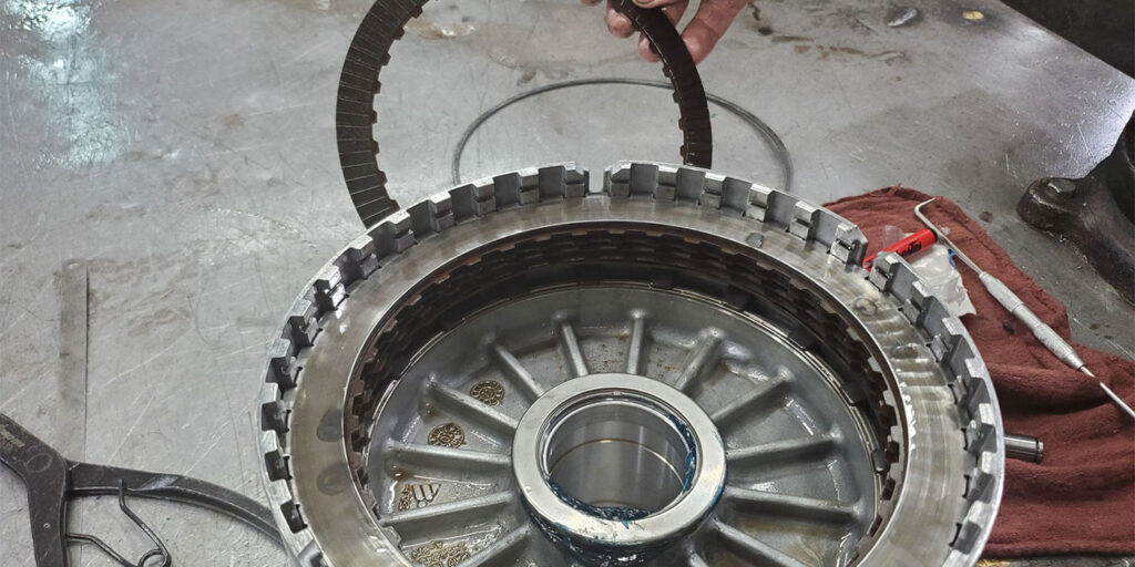
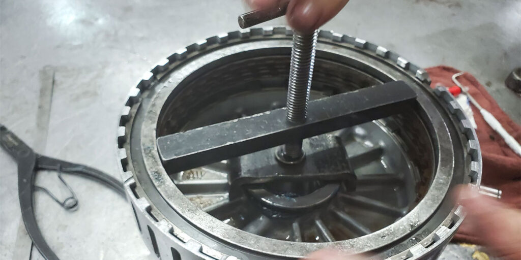
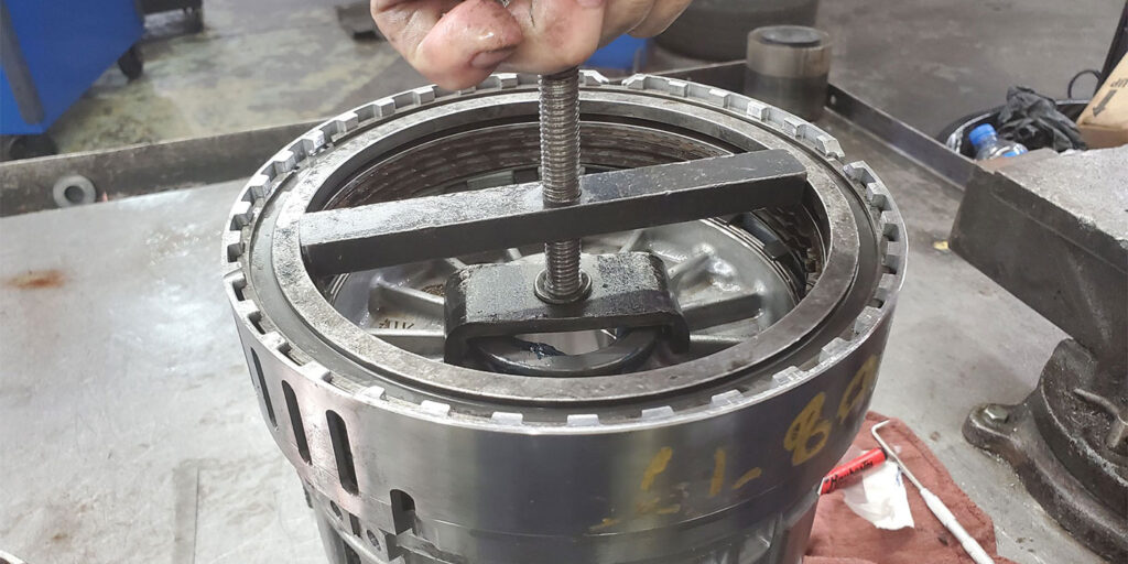
1) I use my L/R piston return spring compression tool to get the job done. I keep the top friction out of the assembly and sit the tool into the housing (figures 1 and 2).

Online-Tip-Figure-1-1400
Figure 1.
Online-Tip-Figure-2-1400
Figure 2.

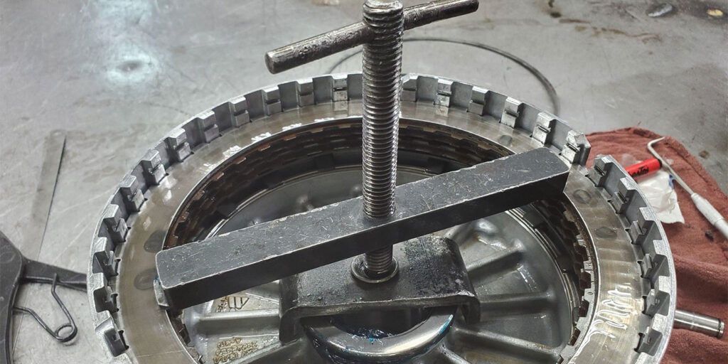
2) I then put the pressure plate in over the top of the tool (figure 3). It fits perfectly.

Online-Tip-Figure-3-1400
Figure 3.

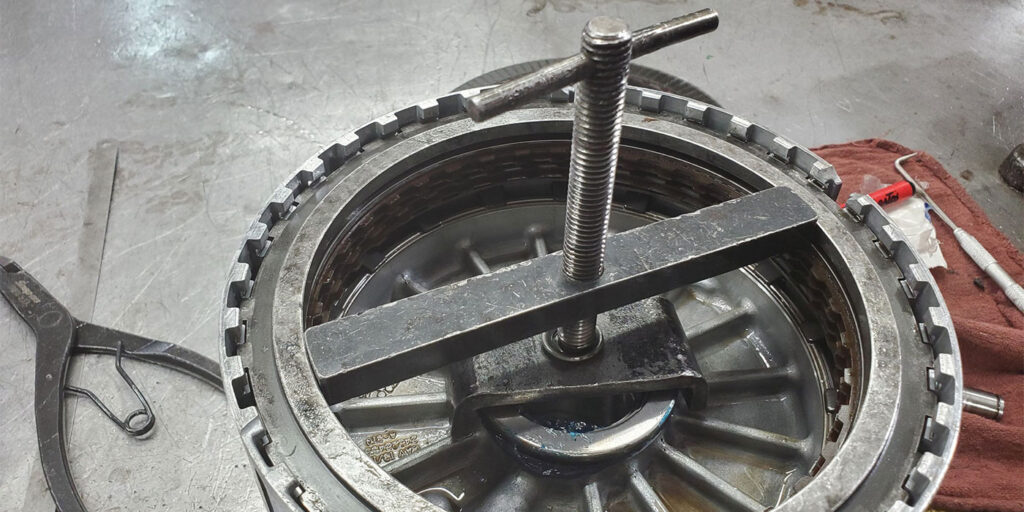
3) I then put the snap ring in (figure 4) and screw the tool down securing the tool to the drum preventing it from wobbling (figure 5).

Online-Tip-Figure-4-1400
Figure 4.
Online-Tip-Figure-5-1400
Figure 5.

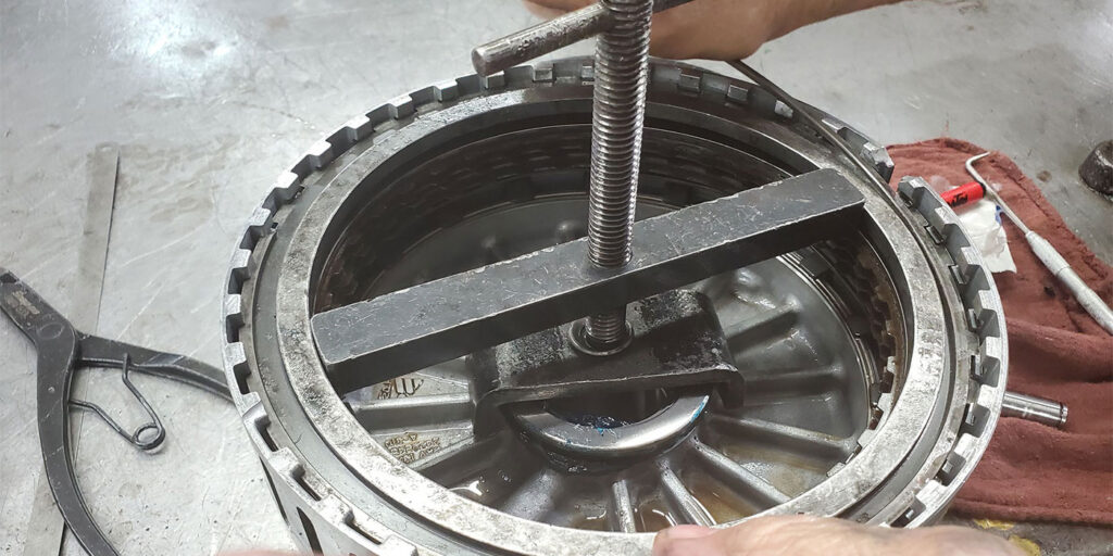
4) Lifting the assembly and putting it in place in the case has become a quick and easy process (figure 6).

Online-Tip-Figure-6-1400
Figure 6.

5) Once in place, I remove the tool, install the friction plate, pressure plate and snap ring. Most shops already have the GM compression tool works with three- and four-speed transmissions. It now can be used with their six-speed transmission.

This article was contributed by Rick Hodgkinson, a rebuilder at AACTION Transmissions in Pembroke Pines, Florida.

You May Also Like

Sometimes, a diagnostic code is all you need

With ATSG having the opportunity to help shops solve problems, sometimes we get faced with some real doozies. A shop will call and give us a laundry list of DTCs, leaving us to think someone must have a bulkhead connector unplugged. We then go through the arduous task of deciding which codes prompted other codes

With ATSG having the opportunity to help shops solve problems, sometimes we get faced with some real doozies. A shop will call and give us a laundry list of DTCs, leaving us to think someone must have a bulkhead connector unplugged. We then go through the arduous task of deciding which codes prompted other codes to set—we’re actually diagnosing diagnostic codes themselves at that point. So, when an issue comes up on our help line with codes that actually tell the story, it makes for a nice change, as well as a quick pathway to a repaired vehicle.

10L80 and 10R80 pump gear differences

You may have seen an article in the August 2023 issue of Transmission Digest called “GM 10L80: A new kind of pump noise,” which goes over how the front cover housing in the 10L80 is fitted with a converter drive gear and idler gear. The idler gear drives the pump’s driven gear, and is press

Shift Pointers: What to do when the 62TE TRS tab breaks

How frustrating it is when on a hot summer day, as you go to open a nice cold can of your drink of choice, and the tab breaks off? You are outside, away from any tools to remedy the problem quickly. It now requires a MacGyver mentality looking around at the resources available to get

Going the extra mile: Proving your transmission repair suspicions

A 2003 Honda Pilot with a five-speed three-shaft transmission came into our shop with a customer concern that the vehicle had no power, and the “D” light was flashing. I first did a scan for codes to see what it came up with, and the scan tool returned four DTCs: P1298 (ELD voltage high), P0135 (H02S

RRfeature-1400
Diagnosing Ford 10R60, 10R80 and 10R140 series speed sensor issues

Ford 10-speed 10R series transmissions utilize four two-wire, Hall-effect sensors — TSS, ISSA, ISSB and OSS — for providing speed signals to PCM or TCM. They are supplied nine volts by a PCM or TCM and assist in the control of clutch apply/release timing that is used in determining shift quality, including TCC. Related Articles

Other Posts

Alto introduces filters for GM 6L series

Alto has introduced a series of filters for GM 6L series transmissions. They include: Related Articles – PRT launches 30 new complete strut assemblies – Force Control Industries releases transmission fluid for oil shear clutch and brake applications  – TransGo introduces 62TE high pressure kit for vans

Sonnax introduces Smart-Tech clutch kit for GM 4L series

Sonnax has introduced a new Smart-Tech clutch kit for optimizing clutch capacity and guarding against clutch burnup in GM 4L60, 4L60-E, 4L65-E and 4L70-E transmissions. This kit (part no. 77734-01K) includes eight .067-in. BorgWarner high-energy frictions and seven .095-in. Lindered steels recommended for use with Sonnax Smart-Tech input housings. Related Articles – OTC releases TJHP15

Shift Pointers: Failures caused by incorrect tire sizes

For years ATSG has produced a wide range of issues related to improper tire sizes on vehicles. Even under-inflated tires have been known to cause issues. Problems such as premature failure with an active 4WD transfer case will occur with incorrect tire sizes. Related Articles – Valve body and component suppliers: A comprehensive list –

Shift-Pointers-Jan-Figure-1-1400
Understanding lube flow control valves in Toyota/Lexus UA/UB80 transmissions

The Toyota/Lexus UA80 and UB80 transmissions first came out in 2017 in Highlanders and Siennas. The UA80 is used in V6 applications, and the UB80 is paired with four-cylinder versions. They have been called Toyota New Global Architecture type transmissions, and alternately referred to as the “Direct Shift 8AT” eight-speed automatic transmission. This transmission was

Tasc-Tip-December-Figure-1---LFC-Valve-OE-Partial-Circuit-Diagram-1400