Up To Standards
- Author: Mike Weinberg
- Subject Matter: Differentials
- Issues: History and current types
We work on drivelines for a living. The transmission makes the torque created by the engine into a usable form through steps (gears), the lowest of which transmits the most usable torque, and the highest of which can transmit the most rotational speed. The transmission sends that power to a third member or rear end, or in front-wheel drive, a rear end contained inside the gear box, without a drive shaft. The rear end now transmits the power to the drive axles and wheels, making a 90° turn through the ring and pinion gears. Transmission gears and the rear-end ratios are matched to the power curve of the engine to provide the most fuel-efficient speeds. The ring gear is mounted to a differential carrier, or in many front-wheel-drive transmissions, a planetary-type of carrier. The differential is contained inside the carrier.
From Open to Limited Slip
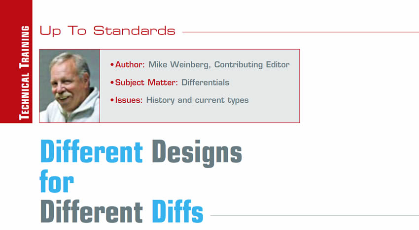
Early automobiles did not have a differential, and the drive axles were locked directly to the ring and pinion. Due to the very low speeds of the early autos, this was not a major consideration at 5 mph. However, as speeds increased, it was very difficult to handle the vehicle in turns without any differential and the vehicle began to crow hop and understeer badly. There was clearly a need to differentiate between the speeds of the drive wheels during a turn, as the inside wheel had to travel a lesser distance, and the outside wheel had to cover more ground. The “open differential” was created, using a set of side gears and pinion gears inside the carrier to allow different axle speeds, which was named “the differential.”
Open differentials (Figure 1) have been around forever, but they have limitations in that only one drive wheel can have power. This creates problems in low-traction situations such as snow and ice, mud and sand. This problem showed up dramatically in race cars of the ’30s where the high horsepower made the drive wheel slip, which limited top speed, wore out tires and created a lot of stress for the driver. In 1935 Ferdinand Porsche asked the ZF company to design a “limited-slip” differential which would be able to send power to both axles when needed but still permit different axle speeds in cornering situations. ZF accomplished this and the Auto Union Race cars of the time (forerunner of Audi) became a force to be reckoned with on the track.
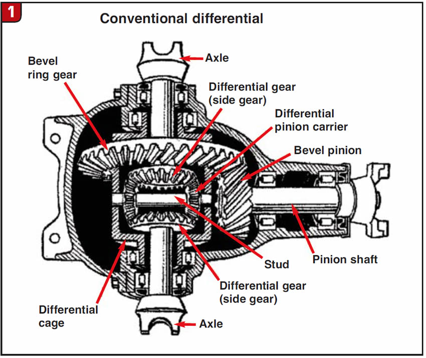
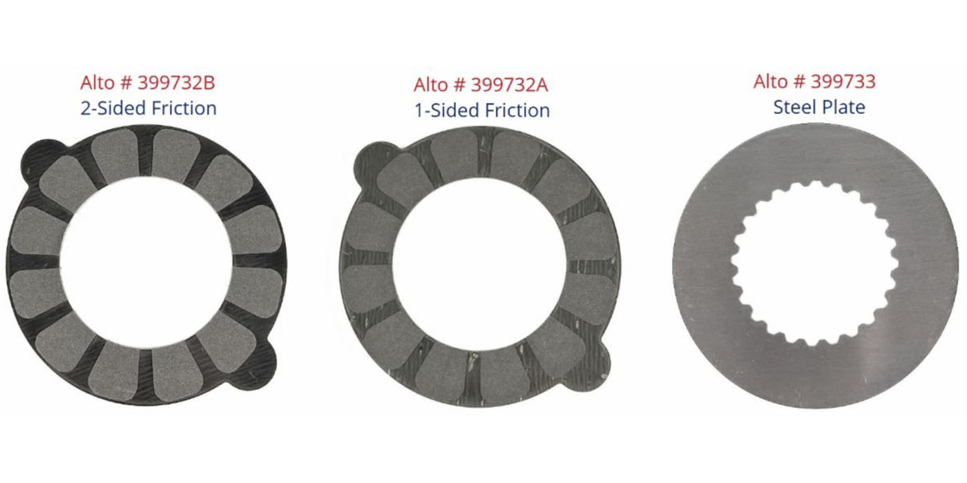
Since that time many different types of limited-slip designs were created, some using spring-loaded clutch plates (Figure 2) to lock the side gears, and some using cone type of clutches on the side gears to do the same thing. These clutches needed special oils to prevent slipping and chatter by providing the correct coefficient in the lube for the clutches to work correctly. A limited-slip differential can transmit power to both drive axles but has limitations as to torque capacity as they provide a fixed amount of torque value, which engine torque can overcome, and have finite limits on controlling lockup of the clutches.

Torque Sensitive
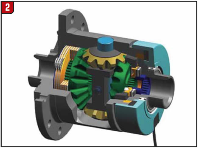
In 1949 Vernon Gleasman designed a torque-sensitive differential that used worm gears to differentiate torque to the axles. The design was sold to the Gleason Corp. and was introduced to the mass markets in 1982 and became known as the Gleason Torsen differential. In 1984 Gleason came out with a second variation that would work with C-clip-type axles and this began to show up in OEM-produced vehicles. This type of torque-sensitive design is capable of much smoother torque transitions, with more flexibility than clutch-type LSDs (limited-slip differential).
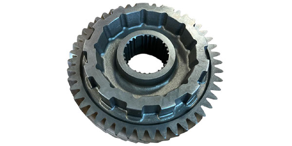
Qualife (Figure 3) has produced and sold a huge amount of this type of differential in Europe, which they call an Automatic Torque Biasing Differential.
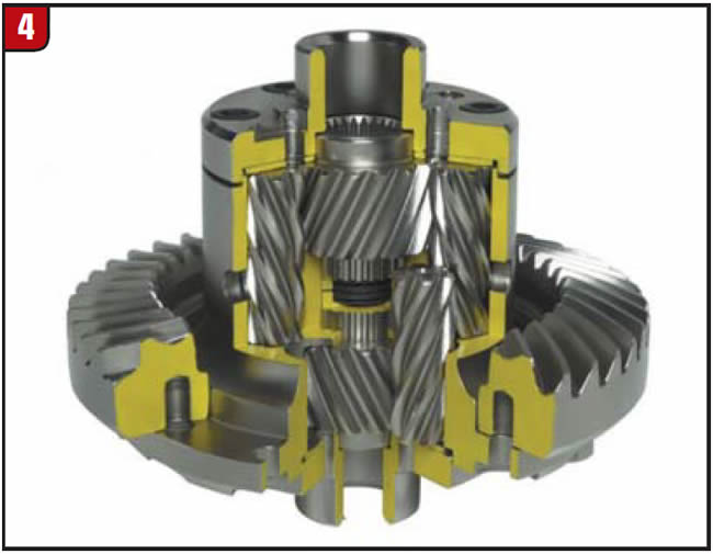
Along these lines American Axle Manufacturing (AAM), Eaton (Figure 4) and Dana have similar product available.
Speed Sensitive
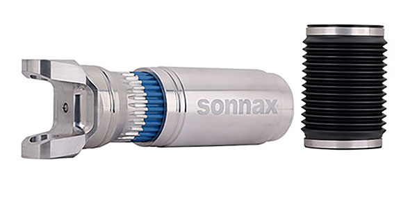
In the never-ending struggle for market share and improved driver comfort, the next design in differentials is the speed-sensitive differential. The first of these utilizes a viscous coupling to lock the axles when there is wheel slippage. The viscous coupling uses a heat-sensitive silicone fluid and alternately splined metal discs in a sealed metal case. When there is wheel slippage between the axles, the silicone fluid expands due to heat generated by the slip and causes the discs to hydraulically lock up sending power to the wheel that needs it (Figure 5).
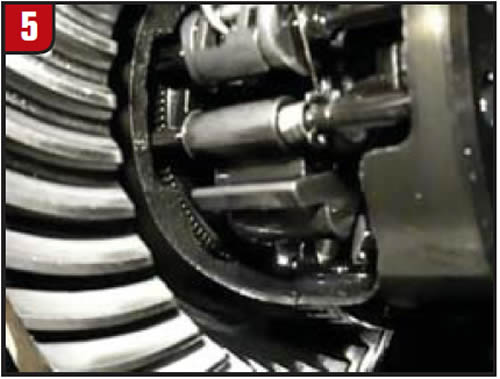
When the wheel speeds equalize, the fluid releases the discs and an open-diff effect returns. Viscous-coupling diffs are very sensitive to heat. A mismatched tire or incorrect tire pressures can fail a viscous coupling, quickly creating an expensive repair. A failed viscous coupling will show up acting like a fully open diff, and under severe overheating can lock up, acting as a spool with tons of crow hop in turns. Another design is the gerotor pump in which hydraulic pressure is created by a pump inside the diff that will apply the clutches during wheel slip, and relax back to open-diff configuration when wheel speeds equalize. Later designs have incorporated computer controls into the gerotor diff to regulate the torque output.
Electronic
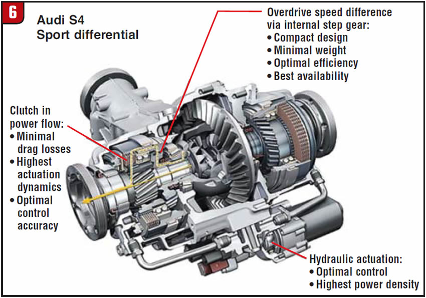
The next level of design is the electronic limited-slip diff (Figure 6), which uses a clutch pack and a planetary-based gear set to differentiate the torque to the axles. These systems are integrated into a computer-driven chassis-management system that can work with 4WD systems, ABS brakes, yaw sensors and stability controls to protect the driver from himself. Subaru, Porsche, SAAB and Cadillac SRX use this type of system.
There are other brake-based systems that use electronics to assist the torque transfer between the wheels by applying selected brake calipers to slow down the slipping wheel and equalize shaft speeds. Understand that a brake-based system will not add torque to the slipping wheel, but applying the brake to that wheel will retard wheel slippage. The problem with these systems occurs when tire size or pressures are mismatched between the drive wheels, causing the system to work all the time, resulting in excessive brake wear and overheating of the caliper on the affected wheel.
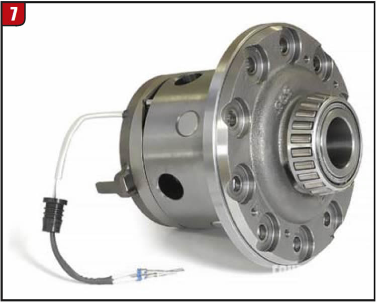
There are two more systems that we should mention, which are locking differentials used primarily for off-road adventures, such as rock crawling with 4WD vehicles. There are many brands available that use either air (Figure 7) or electric to mechanically lock the differentials during low-speed activity such as rock climbing and hill climbs (Figure 8).
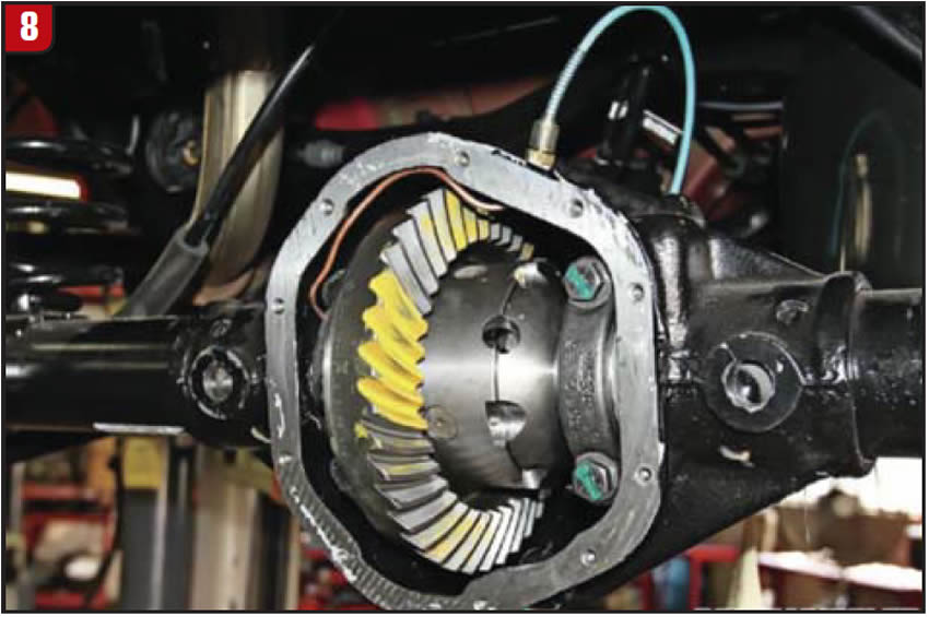
The diff is fully locked into a spool type of configuration with both axles always transferring torque. This works due to the low speeds at which the vehicles are traveling, and the diffs can be unlocked to travel back on paved roads. What started as a very simple idea has been made increasingly more complex as the technology advances. Understanding the operational characteristics is critical to correct diagnosis and profitable repairs.
Mike Weinberg is president of Rockland Standard Gear.