TASC Force Tips
- Subject: Diagnosing a no-reverse condition
- Unit: 4L80-E
- Essential Reading: Rebuilder, Diagnostician
- Author: Randall Schroeder
All too often a problem arises in the shop that just pushes our patience to the limit. Never fails; the customer needed the vehicle last week and is not letting up on the pressure to get the vehicle delivered. When time demands become overwhelming, such as in this scenario, it is very easy to get sidetracked. In our rush, we often ignore the diagnostic basics that would have led us to the root of the problem. A real-life situation reminded me how we all fall into this trap and need to remember that diagnostic time typically saves money vs. guesswork, which can be very expensive when it does not work.
Diagnosing a shift concern can be easy, as long as you understand some basic techniques to help get to the root of the problem. A reliable and orderly diagnostic approach is splitting the circuits. Splitting the circuits means separating and analyzing the hydraulic, electrical and mechanical issues that could create the problem. Let’s follow through the flow of diagnosis in this one together. Make sure you have the following on hand: a line-pressure-test spec sheet with test-port locations, and a clutch and band chart to help eliminate other areas that may be associated with the problem shift.

Step 1: Split the circuits “hydraulically”
When dealing with slipping, chatter and/or individual shift failures, it is very important to see whether the line pressure that is directly associated with that one shift is out of specification. This means that the pressure test must be done in that specific gear. Also, use the clutch and band application chart to see whether the component of concern is used in a different gear range, and make the pressure test in that gear range as well. In the case of no reverse, the players inside the transmission are:
- Direct clutch (also used in 3rd and 4th gears)
- Low/reverse band (also used for engine braking in manual 1st gear).
Knowing this, we want to test the line pressure with the transmission in reverse, 3rd, 4th and manual 1st. Verify that both the low side and the high side of line pressure at each of the shifts are within the pressure-test-chart specification. To test the pressures for 3rd, 4th and manual 1st, we will have to go on a road test while monitoring the pressure gauge. IMPORTANT: Make sure that the pressure gauge is secure for the road test and easily viewed (remember, keep the pressure gauge on the outside of the vehicle if it is a mechanical gauge. This will prevent oil from ending up inside the car if there happens to be a leak from the gauge or hose). Depending on the test results, we know the following:
- 3rd and 4th gear are present: we know the direct clutch is capable of working and is good
- 3rd and 4th gears not present: There may be an issue with a checkball leaking or missing in the valve body, and/or something with the seal rings and/or direct-clutch drum fault.
- Engine braking in manual 1st: we know the low/reverse band is capable of holding.
If there was no engine braking in manual low, there may be a mechanical issue with the low/reverse band (we will confirm this in the last part of these three test areas) or a valve-body issue such as a missing or leaking checkball. This will be separated during the mechanical test to know where the problem area is. No engine braking in manual 1st is a great clue that may lead us to the band, but there are still other factors to look at. Remember, splitting the circuits means separating the hydraulic, electrical and/or mechanical issues that can create the problem. The first step was verifying pressure.
Step 2: Split the circuits “electrically”
Splitting the circuits electrically is a basic step in diagnosis of the no-reverse shift concern. Electrically controlled transmissions generally have a built-in safety program that prevents the transmission parts from breaking on the basis of a rolling-speed shift reference during the reverse engagement. If the control module senses a speed reference greater than 8 mph during the shift into reverse, it has the ability to prevent the shift from happening.
That being said, eliminating the electrical part of this one is a simple test. Unplug the electrical connector to the transmission (this will force a failsafe shift pattern, eliminating the computer’s ability to prevent the shift) and see whether the reverse shift comes back. Understand, sometimes this test can be misleading: If there is a subtle hydraulic leak in one of the containment areas, the leak may be overcome with “max” line pressure. With the case connector unplugged, line pressure will go to an uncontrolled max value that can mask a leaking concern inside the unit.
Answers to the test results of case connector unplugged:
- Reverse works: follow electrical diagnosis and check for speed references to control module
- Reverse fails: on to the mechanical test!
So far, here is what we know in helping to find the no-reverse issue.
- Line-pressure issues can be eliminated easily with a simple test.
- Electrical issues can be eliminated easily with a simple test.
This leaves us with the last of the three diagnostic areas: the mechanical part.
Step 3: Split the circuits “mechanically”
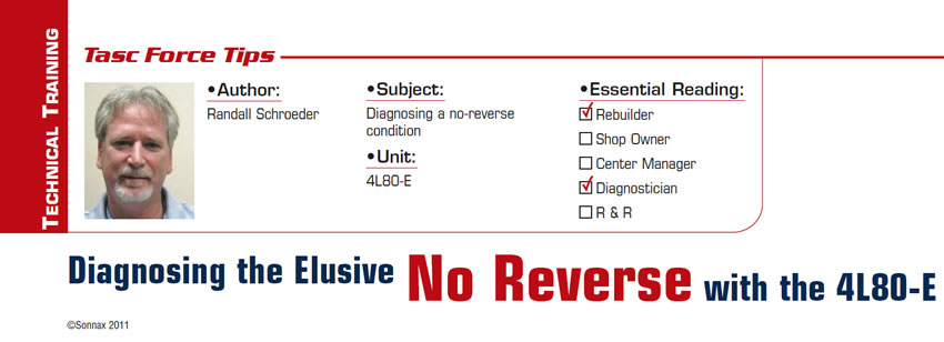
For this no-reverse shift issue we are going to mechanically split the circuits by blocking the low/reverse band. To do this, we need to have the oil pan removed. It is a very simple procedure and can be done two different ways. First, make up a special tool that will allow you to manually lock the servo down. To do this, use an old servo cover and drill a hole down the center of the cover. With the hole drilled, weld a nut on top of the cover to allow the use of a bolt to lock the band tight (mechanically) (Figure 1). Once you have the tool installed there are two ways to do the test. One can be very messy if you are not prepared for the test, and one is clean, as the oil pan is reinstalled onto the transmission. Let’s look at the two tests:
• Pan off: Install test cover for the low/reverse band. You will need to make a second tool from an oil pickup tube off of an old filter (cut the neck off the filter and clean it for the tool). Install a rubber hose onto the tube, making sure that the hose is long enough to reach into an oil-filled bucket and allow the pickup tube to be installed into the oil pump. This is a fast test but is messy, so be careful. It is a good idea to hang a plastic shield around the transmission to direct oil into the catch bucket! Start the vehicle in neutral with the parking brake applied (this helps in preventing the mess), and quickly shift to reverse to verify whether the band is holding with engine load. Note: If you happen to start in park and shift to reverse, it will squirt oil (big mess). Question to be answered: Does it now have reverse? This is the messy test!
• Pan on: Much cleaner test, but also takes much longer to get the answer. Install the locking tool onto the low/reverse servo. Make sure that the bolt on the locking tool allows the oil pan to be reinstalled and fill the pan with oil. With the oil pan installed and filled to the proper oil level, make the shift test to see whether you now have reverse with the parking brake applied. Does the engine hold back? This is the cleaner test!
If during the test our answer gives us a positive shift into reverse, we know there is a band-application issue that typically can be resolved without removing the transmission. Remove the valve body and check for blockage in the low/reverse-servo feed passages in the case and/or the separator plate with gasket issues. While the valve body is on the bench, carefully inspect the body for valves sticking and make sure that there is no issue with checkballs #7 and #11, which are housed in sleeves in the valve body (both have been known to cause issues).
If there is still no reverse during the test, the transmission must be removed for inspection to make sure that there is nothing in the direct-clutch drum (remember, there are two separate apply areas for reverse vs. 3rd and 4th gears in the direct-clutch drum) and that the band is clamping properly on the drum to hold for reverse.
Inspecting on the bench
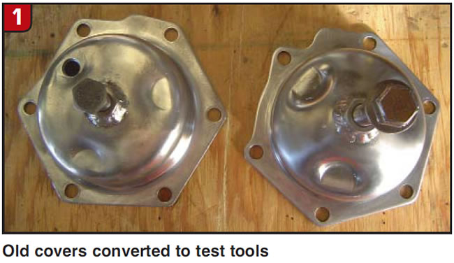
Dismantle the transmission to the point of being able to see the direct-clutch drum in the case with the valve body removed. Make a simple air test to the direct-clutch through the case to verify that both the feed passages apply and hold. If it fails this test, remove and verify problem areas in the drum or on the support, and retest. Air test for the drum passages; remove the drum and the center support/second-clutch drum from the case. Visually inspect the band and the drum for broken pieces (Figure 2).
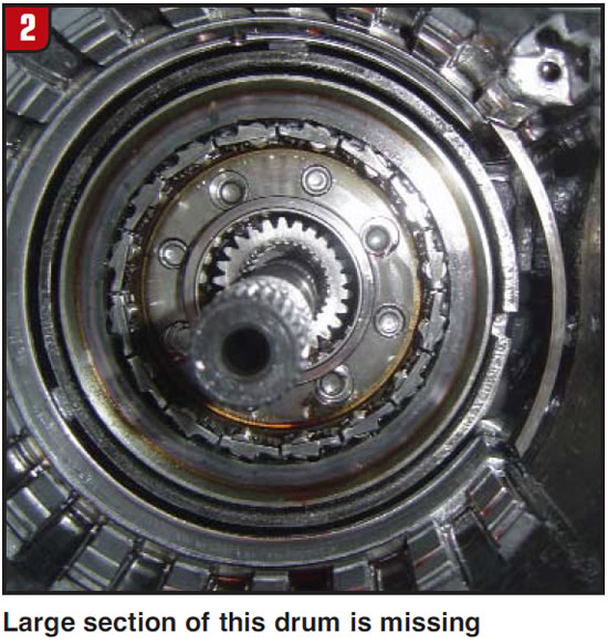
Install the special test tool that allows the band to be mechanically applied (Figure 3). Lock the band tight and verify that the band ends do not touch, preventing a positive lock on the drum.
Important to note: Installing an improper band is a common cause of no reverse after repair because of rapid wear. Why does this wear occur? In the 1995 model year there was a change in both the surface of the drum and the lining of the band. In addition, there also was a change in the boost valve in the front pump for reverse line-pressure boost. The differences in the bands are clear (Figure 4).
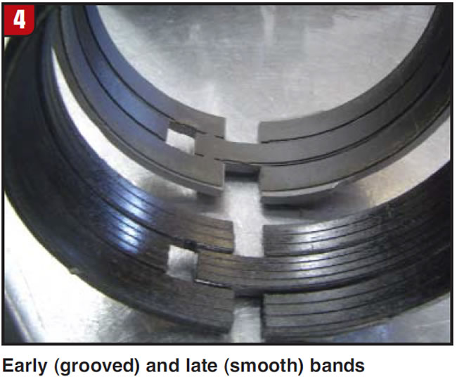
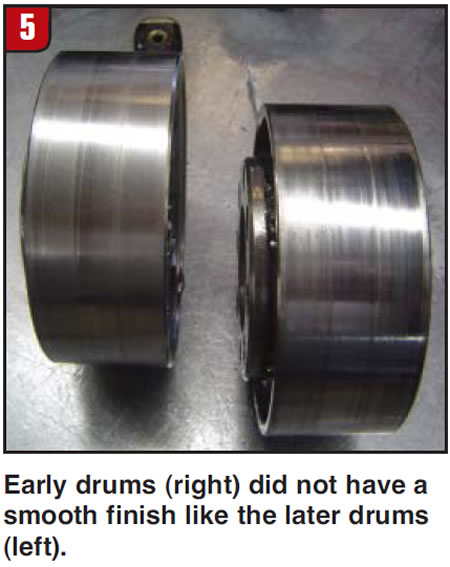
Early bands had a grooved lining, and later bands were smooth-lined. Along with this change, the surface of the drum is critical for the life of the band. Early drums did not have a smooth finish on them to allow for the use of the grooved band. The late drum is smooth-finished to allow use of the smooth-lined band (Figure 5). If you happen to put the smooth-lined band onto the drum that has the rougher finish, the band will fail, causing the lining to be removed (no reverse).
Diagnosis often seems as though it takes too much time, but in the grand scheme of things, diagnosis truly saves time. Remember the simple rules in diagnosis of separating the three areas of the transmission (hydraulic, electric and mechanical), as this does save that valuable time. Let’s all be successful; keep those tech tips coming.
Randall Schroeder is a Sonnax technical specialist and a member of the TASC Force (Technical Automotive Specialties Committee), a group of recognized industry technical specialists, transmission rebuilders and Sonnax Industries Inc. technicians.
©Sonnax2011


