R&R Tech
- Author: Dan Frazier
- Subject Matter: Waveforms
- Issue: Interpreting data
I’ve always had been fascinated by technology and electronics, and I can remember the first time I used a scope. It was in my high school auto-tech class, and we were being intro-duced to ignition waveforms using a Sun Engine Analyzer. I pulled my 1968 Barracuda up to this huge machine with all kinds of leads coming off of this big arm that hung over the engine bay, and everyone in the class was overwhelmed by what was going on. It was amaz-ing to me that my teacher could tell that my points (anyone remember points?) weren’t gapped properly and that I had a bad plug or wire on #3 cylinder simply by looking at the electrical signal on the scope.
Fast forward 40 years – Now we have four- to eight-channel lab scopes that are built into your scan tool or laptop that are capable of storing and manipulating data at the click of a mouse. We have multiple computer systems controlling every aspect of how our vehicles operate. Just turning on a dome light requires computer requests and verifications from multiple modules. Making a transmission shift is a whole different story. If I’m the PCM or TCM, I have to know if I’m receiving the correct information from other modules, usually on some form of data bus, various sensors, and the list goes on. Same with the airbag mod-ule and ABS/traction-control module, and keeping track of what module has control over each function can be a tedious task.
A majority of the time, a lab scope is a good way to verify inputs and outputs to various controllers. Sometimes, it’s the only way. Graphing data on your scan tool can reveal many things, but often scan tools are just too slow to pinpoint the problem. Using a lab scope, we can get a complete picture of the electrical signals that the module in question is receiving. Add an amp probe and a pressure transducer to the mix, and we can get a comprehensive look at the signals in real time.
Let’s take a look at a couple of cases that would seem to be simple but turned out to be a little more involved than expected. This is where experience in diagnosing electrical signals with a scope comes into play.

Ford F-550: 3 issues
The first case is a 2004 Ford F-550, equipped with a 6.8L V10 and a 4R100 transmission, with PTO. It came to me with an issue of the O/D light flashing, erratic shifting and code P0717 (no turbine speed signal). On my initial inspection, the transmission did shift through all four gears, although very erratically, and the O/D light started flashing after the first couple of shift commands. I had no turbine speed sensor on the scan data, so I knew I needed to check out the TSS circuit to start with.
I usually use my ohmmeter to check for open or shorted circuits; I really don’t trust it for much else because it doesn’t send enough current through the circuit you’re testing. Volt-age-drop testing is preferred for finding excessive resistance from bad grounds, poor con-nections, etc., and you can often find a corroded wire or circuit by doing that. In this case, the sensor tested within range, but then I went to the PCM and checked the resistance be-tween the TSS input terminal and sensor, and I found an open circuit. Slam dunk, right? I knew I had a broken wire on the TSS circuit to the PCM. I installed an overlay wire from the PCM to the sensor connector at the transmission, thinking I was good to go, but no – I still had no TSS signal to the PCM.
So, what’s up? According to my ohmmeter, I had a good circuit between the PCM and the sensor. How do I verify that the circuit is capable of sending a signal to the PCM?
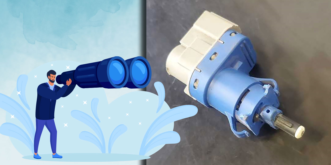
Actually, it’s pretty simple: The TSS sensor on this transmission, like many others, is a variable reluctance sensor. Simply put, it’s a coil of wire wound around a magnet, and any movement of a metallic object – tone ring, reluctor (there’s lots of names for them) induc-es a voltage as the metal crosses the tip of the sensor. It doesn’t have to have any power supplied to it, unlike a hall-effect sensor, to operate.
I took the sensor out of the transmission and hooked up my lab scope to the signal wire at the PCM. I had an assistant take a pocket screwdriver and wave it over the tip of the sensor really fast. I could see that I had a waveform (although erratic as expected) to verify that the sensor and the circuit were both intact. It looks like this:
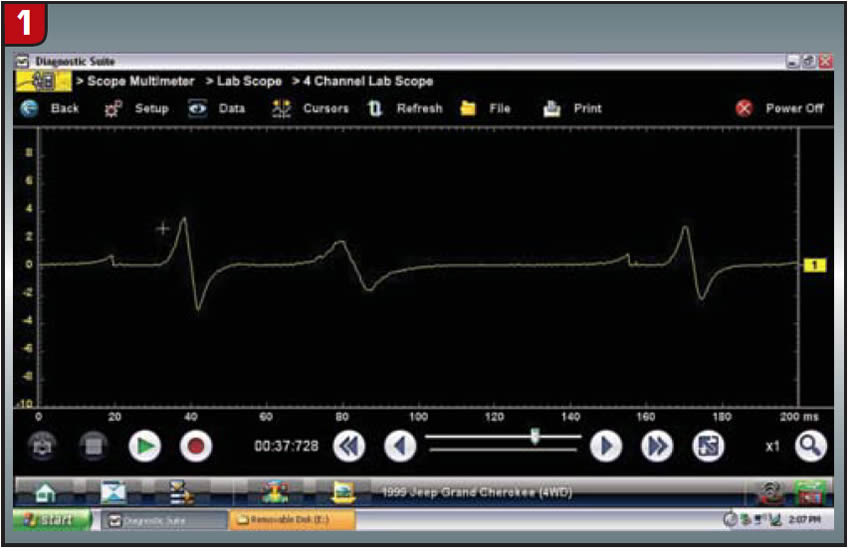
You can do the same thing with a hall-effect sensor, which usually has three wires, power, ground and signal – just turn the key on. But a hall-effect sensor will produce a square wave of some sorts using this method instead of a sine wave.
As it turns out, there was an internal failure of the transmission. The TSS signal is gener-ated by the teeth on the coast clutch drum, and for some reason it was not spinning, alt-hough the transmission did shift through all four gears. Going one step further, I took a mirror and looked through the sensor-mounting hole which is easily accessible on this transmission. I had an assistant start the engine and put it in drive and let the wheels spin. Sure enough, I could see the drum spin for about two seconds and then come to a stop. I didn’t tear the unit down to determine the exact cause of the failure, but I knew from the scope data and visual inspection that it was an internal issue.
Self-inflicted
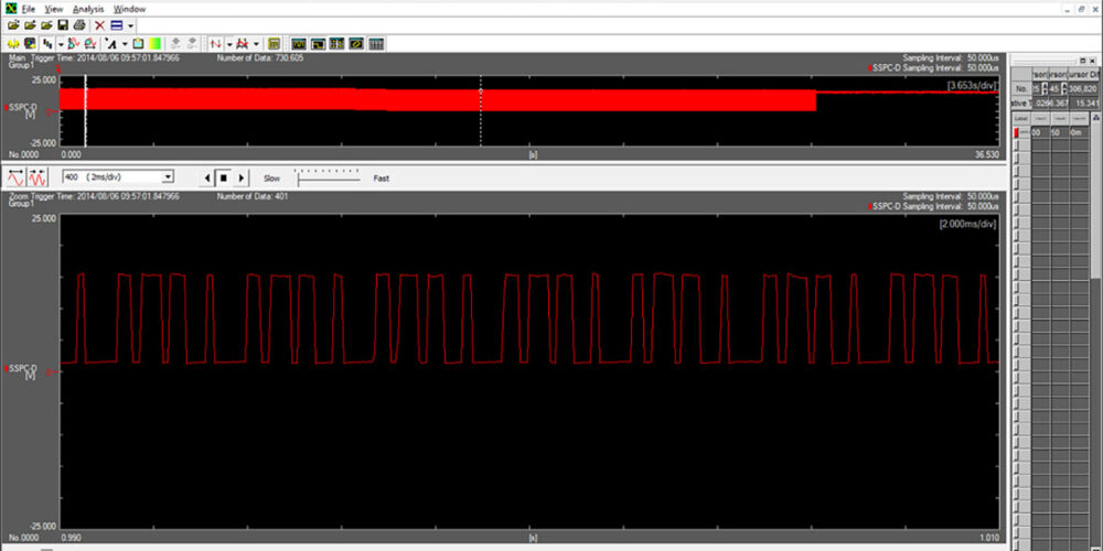
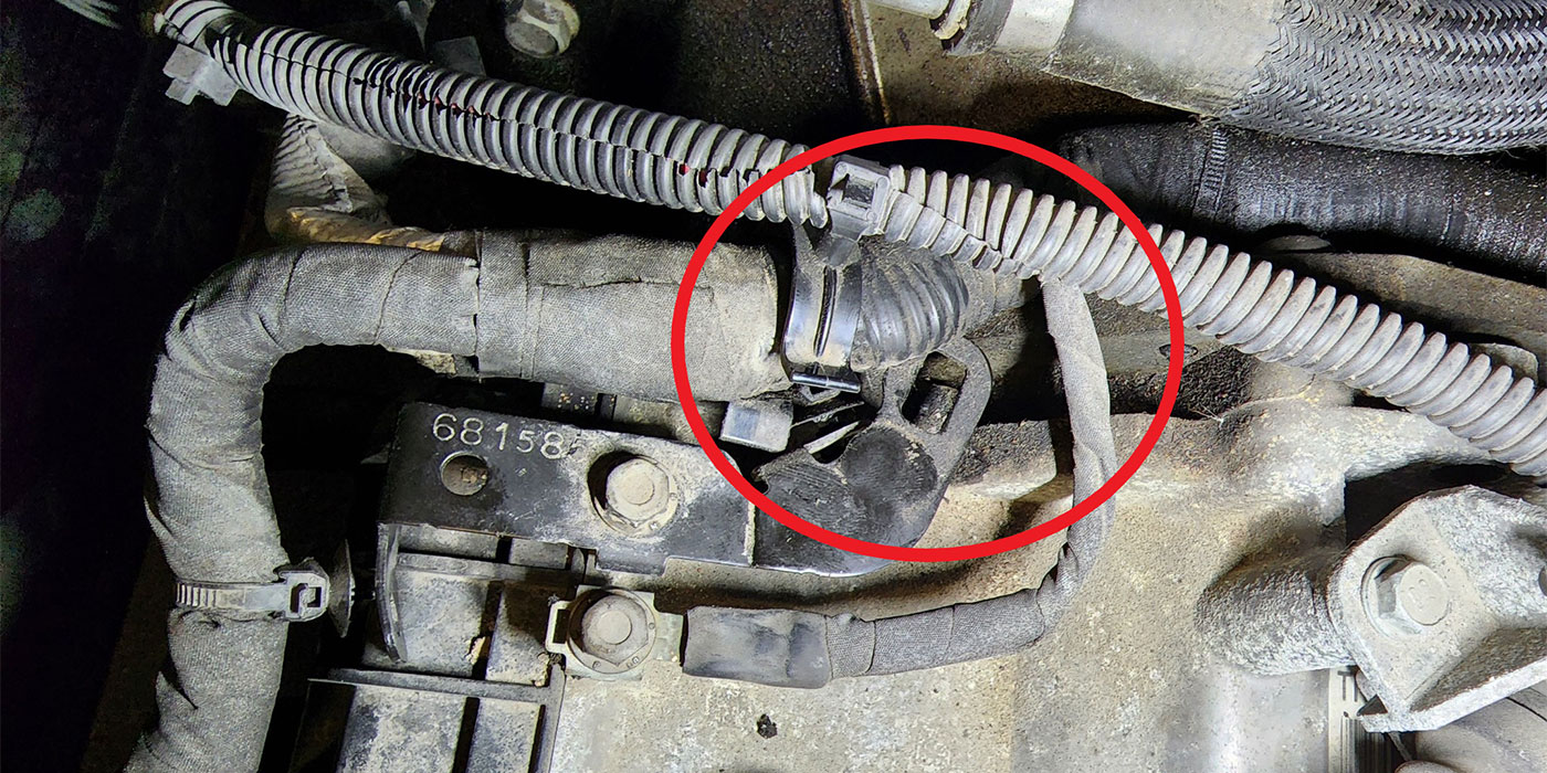
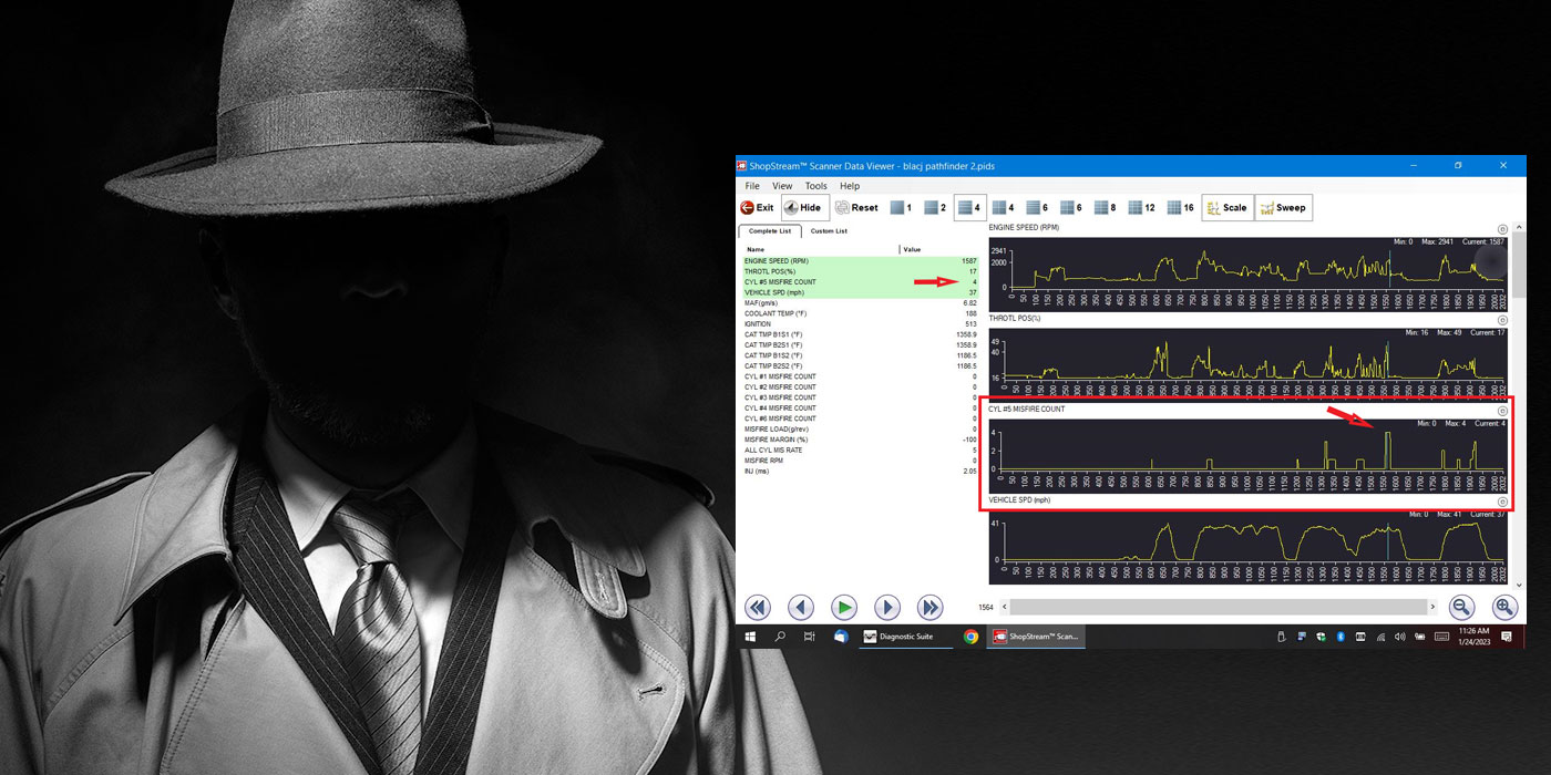
The next case is very similar: a 2006 Ford Focus that another shop had installed a reman unit into and would turn on the MIL after about a mile or so of driving, and set code P0721 (excessive noise on the output speed sensor circuit). It shifted fine and graphing the OSS showed no glitches or dropouts of the signal. This turned out to be a man-made failure – a self-inflicted gunshot wound, if you will. Here’s a picture of the waveform from the output speed sensor:
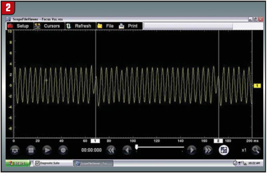
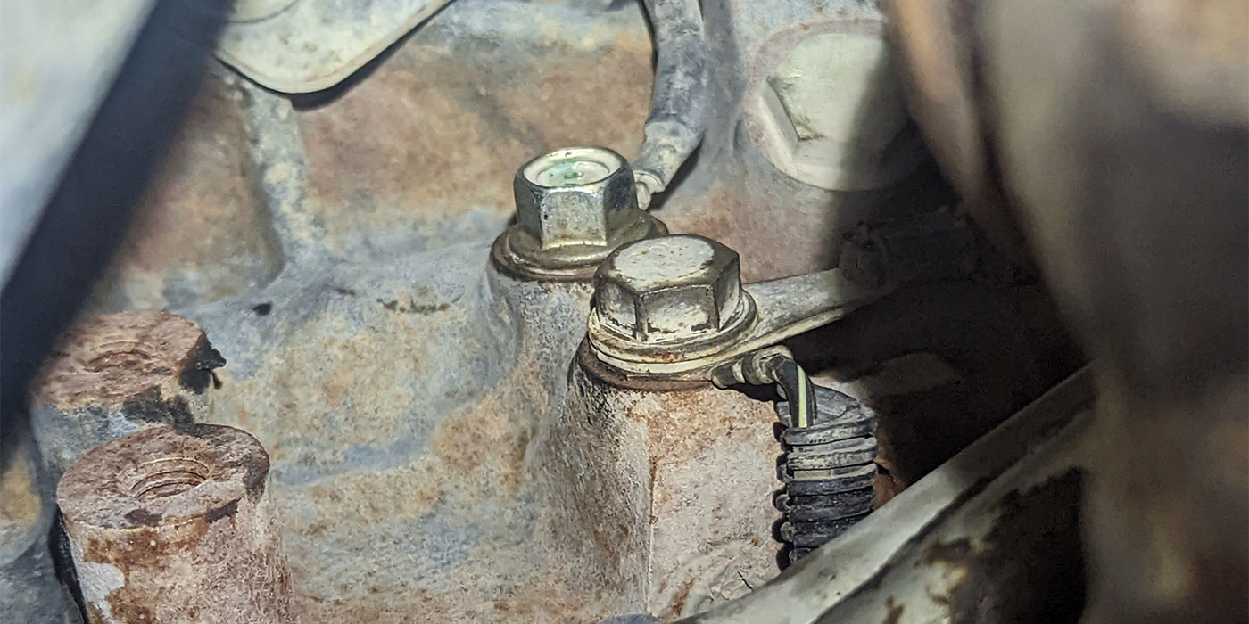
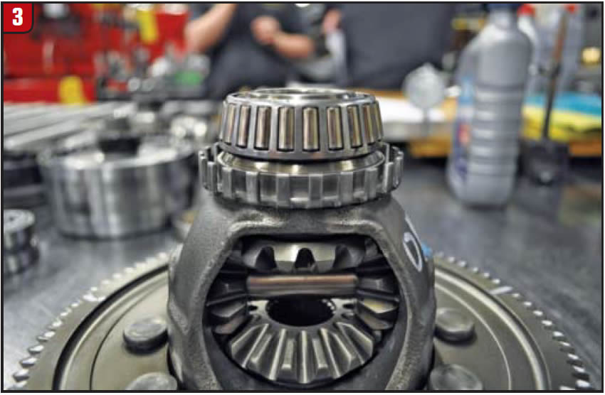
Notice the one hump in the waveform that the amplitude is about half of what it should be where the cursors are? What had happened was that the tone ring for the OSS got slightly bent somewhere during the remanufacturing process. As you can see by another picture, the tone ring under the side bearing could very easily get one of its teeth bent, and it wouldn’t take much of a bump to bend one enough to disrupt the signal:
I actually tried to measure the depth of the teeth through the mounting hole for the OSS with a caliper – it’s pretty easily accessible – but couldn’t really identify the bent tooth. This puppy couldn’t have been bent more than 0.015 inch. I even tried to bend another tooth up to provide a point of reference, thinking if I could find my high tooth, I could count the number of teeth to my low tooth and try to pull it up with a pick. It just didn’t work out; I was trying any means possible to have to avoid R&R the transmission, but no dice.
There are many times, unfortunately, that a simple mistake can lead to a complicated di-agnosis. Anyone ever seen a late ’90s Jeep flexplate disrupt the crank sensor signal because someone got in a hurry and bent the window on the flexplate ever so slightly, but just enough to cause a misfire? Ever had a cylinder head come back from the machine shop with the cam sensor reluctors bolted to the wrong cams? Or one of my favorites, a used car lot swaps a 2.7L Chrysler motor from the wrong year, and the cam sensor signals are en-tirely incompatible due to design and computer strategy? That all comes from my days in general repair, but it’s things like that that apply to everyday situations and can usually on-ly be found with a lab scope.
So, how do we know what a good scope pattern looks like vs. a bad one? Firstly, there may be many good known waveforms already stored on your scan tool or scope. Secondly, there are a lot of known good and bad waveforms on websites or in factory service information. One of my favorites is IATN, as that site has a pretty extensive library of waveforms, scan data, and input from thousands of automotive professionals like us. Lastly, use your scope when you get the time to look at a known good waveform, whether it be checking current to an EPC solenoid, or voltage to a shift solenoid for a voltage spike. The more you use it, the easier it becomes to get proficient at diagnosing electrical problems, and everyone prof-its from it.
Dan Frazier is a diagnostician at Certified Transmission’s retail location in Grandview, Mo. An ASE certified master technician, he has been in the automotive industry more than 30 years.