
TASC Force Tips
- Author: Bob Warnke
Vehicle restoration is a time-consuming process. Some projects remain scattered about the garage much longer than planned or appreciated. The definition and effort involved with detailing vary with the type of vehicle. An off-road Bronco probably gets a last set of decals, whereas the vintage collector gets paint and buffing.
If you have ever power-buffed a paint finish, you realize that if you stay in one place too long or use an aggressive polishing compound, eventually the finish will buff out and then off. That’s probably not a concern on the Bronco destined for the woods, but on the ’67 Camaro, it’s not good.
Detailing also refines the interior. I recall a used-car account that routinely dropped off vehicles for “quick jobs.” One had repetitive electrical issues, returning this time with an inoperative power window. After removing the trim panel, I found the door was compacted above the motor with dried mud. If this had been a Bronco, with roll cage and big tires, it could have been explained with a good story behind it, but this was a luxury car. I would presume when they “replaced” the interior and cleaned out the soft mud, the doors had been overlooked. In appearance, both the interior and exterior of the car were detailed perfectly.
Body detailing is much like transmission work, in that a thorough job requires time and experience. Years ago we were cleaning cast drums and shafts to avoid flushing the material back into the governor. Today, debris is attracted to a solenoid or sensor by its magnetic field.
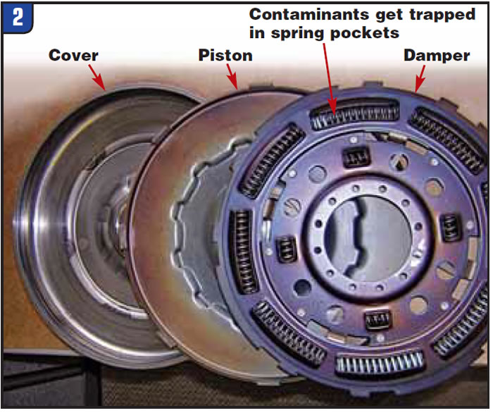
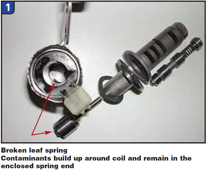
The material also can be held by centrifugal force, such as in the converter damper.
Generally the abrasive material becomes embedded, but when fresh fluid is added or a temperature or pressure rise occurs, it is disturbed. The suspended material is then free to polish away at the valve body and solenoid bore, just like the power buffer going through paint.
To illustrate various degrees of the wear process, the casting shown in Figure 4 is a good example of bore wear from the 47RE governor shift plugs.
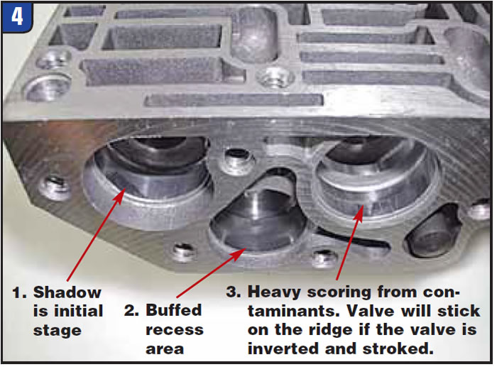
In most instances, bore wear is hidden and you must inspect the casting at different angles along with additional lighting. The loaded side of the casting will wear first. Loading is generally from the force of the fluid pushing against the surface of the valve, causing the spools to rub hard against the casting. Valves that have stout springs load both end spools in a pattern 180° apart from each other.
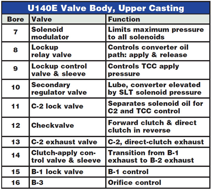
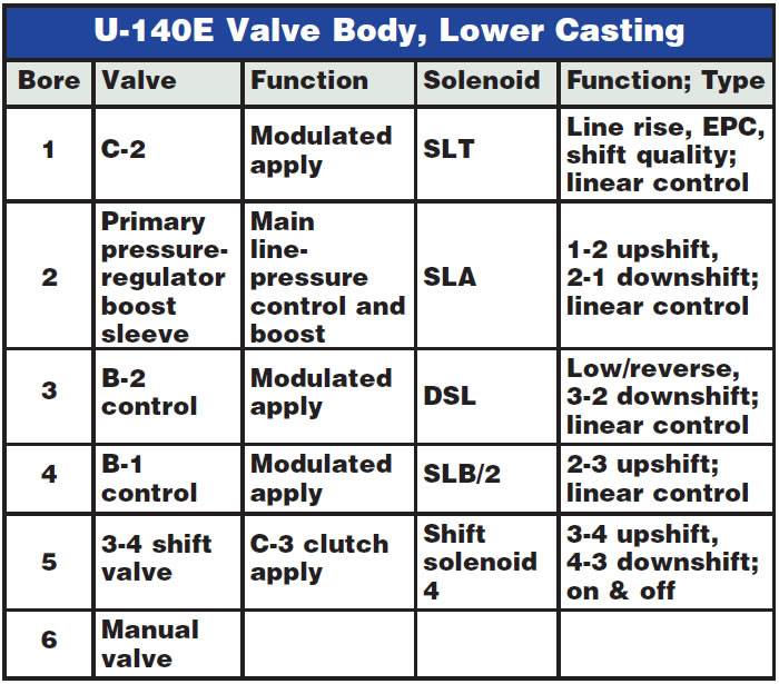
Visual inspection requires complete disassembly. In Figure 5, the ink marks (halfway down bore 7, for example) indicate critical points for visual inspection on this U140E valve body. The ink marks at the end-plug retainers (such as bore 12) indicate they must seal. (The chart below identifies the upper-valve-body bores in Figure 5 and their functions.) These end plugs and all the circuits with the ovals drawn around them in figures 5 and 6 can be vacuum tested. The chart in this page’s second column identifies the lower-valve-body components shown in Figure 6.
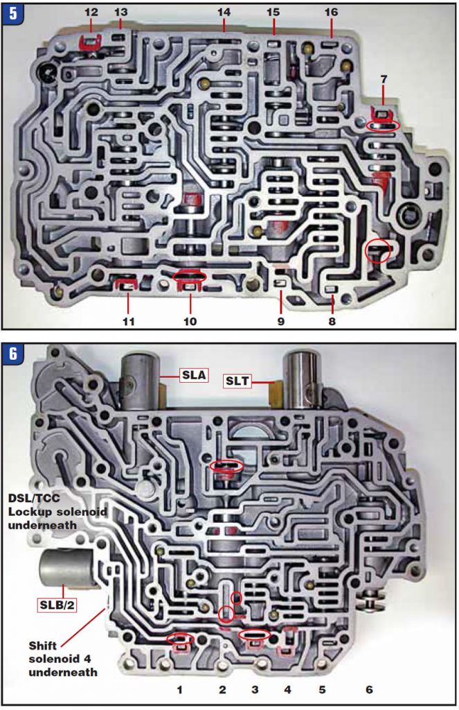
A calibrated vacuum-test station is required to perform the vacuum test and to apply the pass/fail example standards given here. Once a system has been set up and calibrated it has a repeatable outcome and provides reliable data. Vacuum testing results in a specific value rather than a judgment on wear and leakage. Acceptable tolerance readings are typically 19 inches or better when you’re pulling a vacuum over one spool and 17 inches plus when you’re isolating two spools.
This test is not a shortcut to detailing or cleaning and may require foam pads or plates to isolate some circuits. The U140E is not easily vacuum tested because some circuits pass over both sides of the casting. The circled areas on the photos indicate effective U140E vacuum-test points that will not require a special plate. Visit www.sonnax.com for information on setting up a vacuum-test station.
In the older units without linear or variable-force shift adaptation, we could compensate for a circuit loss by opening a clutch-feed orifice. Generally, that has no effect on a unit with a TCM controlling the clutch-apply and feed pressure. To a certain degree, the solenoid output can be altered by the TCM to compensate for wear, relying on adaptive strategy or TAP cell. Once the valve tolerance becomes excessive, adjustment is beyond what a TCM or solenoid can alter. Another alternative is to elevate line pressure or clutch pressure to shorten shifts. This will cause the TCM to react and back off in either case.
Finding the root cause of a problem is comparable to restoring the vintage look and feel of a fine car (Jeep, Bronco etc). That sense of accomplishment or relief is comparable to the moment you roll the project vehicle from the garage and your wife gets the parking space back.
If you’re getting into this U140E or the U240E, ATSG has a Technicians Guide with full oil circuits and exploded valve-body views.

Bob Warnke is Sonnax vice president of technical development and a member of the Sonnax TASC Force (Technical Automotive Specialties Committee), a group of recognized industry technical specialists, transmission rebuilders and Sonnax Industries Inc. technicians.


