


The owner of a 2004 VW Jetta was experiencing an erratic condition in regard to how the transmission was operating. At times, the check engine light would go on while driving, but then go off after the ignition key was cycled, only to return once the vehicle started to move.
The vehicle was equipped with a 1.9L engine and had a five-speed JF506E transmission with 82,000 miles on it. With no check engine light on, the unit worked fairly well; however, when the light came on, bad things started to happen. The transmission then had fairly hard upshifts in conjunction with no 5th gear. Beyond that, the speedometer failed to register until the vehicle got up to approximately 15 mph, at which time it started to work. A scanner was connected to identify any trouble codes. The only code that surfaced was a 00281, which is comparable to a P0720 (VSS/OSS – output speed sensor circuit failure). After reviewing the drivability issues, including harsh shifting and no fifth gear along with a wacky speedometer and in conjunction with the trouble code, a bad speed sensor is definitely indicated.

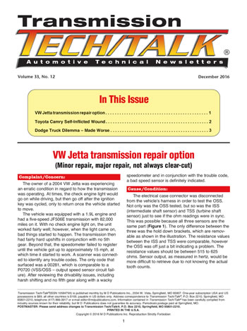
The electrical case connector was disconnected from the vehicle’s harness in order to test the OSS. Not only was the OSS tested, but so was the ISS (intermediate shaft sensor) and TSS (turbine shaft sensor) just to see if the ohm readings were in sync. This was possible because all three sensors are the same part (Figure 1). The only difference between the three was the hold down brackets, which are removable as shown in the illustration. The resistance values between the ISS and TSS were comparable, however the OSS was off just a bit indicating a problem. The resistance values should be between 515 to 625 ohms. Sensor output, as measured in hertz, would be more difficult to retrieve due to not knowing the actual tooth counts.

Dealing with a sensor replacement is no big deal, or at the very most a little time-consuming; however, such is not the case when it comes to a JF506E transmission. For some reason, when Jatco was developing this unit, they decided to bury not only the OSS but also the ISS deep inside the transmission, which renders easy replacement null and void.
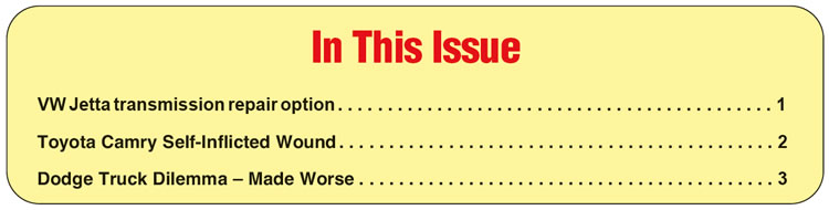
To start with even removing the transmission from this vehicle is no walk in the park, which is why flat rate to do this work is approximately 14 hours. With the transmission out of the vehicle, the bell housing has to be removed to expose the sensors (Figure 2). At least the pump and gear train doesn’t have to be pulled.
As illustrated, the sensor on the left, which is below the park gear, is the OSS. The ISS, which is on the right, is below the transfer drive gear. The OSS at this point could be replaced and the vehicle sent down the road; however, prudent judgment dictates that both sensors be replaced due to the effort it took to get there.
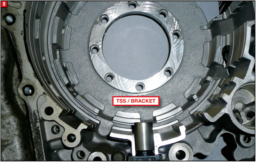
As stated, there are not two but three RPM sensors in this transmission. It’s not much of a stretch to recommend replacing the TSS, which is at the other end of the transmission. Merely remove the end cover to gain access to the TSS (Figure 3). All three sensors were installed by Jatco at the same time, therefore it would make sense to replace them all at the same time, just like tires.
The unfortunate part of this scenario is that the customer has to pay a considerable amount to correct the problem, unlike most other applications that would cost a fraction to do. The most important thing is that shop personnel are aware of situations like this upfront to avoid a confrontation with the customer later on.


The owner of a 2010 Toyota Camry started to experience an erratic shift condition although the vehicle only had 72,000 miles on it. Up to that point everything worked well and the car owner was diligent about the maintenance schedule so it came as a surprise when the transmission started to get ugly. Reluctantly, the car owner brought the vehicle in for an evaluation and as expected a transmission problem did exist.
During the road test the vehicle was driven under different conditions and the main concern ended up being an inconsistent 3-to-4 upshift. At times, the shift produced a slide bump feel or occasionally an engine flare-up and the temperature didn’t seem to have much effect. The vehicle was equipped with a 2.5L engine and U760E six-speed transmission. The U760E is a slightly lighter version of a U660E and does have several parts common to both models. There was no check engine light or trouble codes stored.
Although there has been valve body and solenoid issues with this family of transmissions the decision was made to remove the unit and perform an internal inspection. With the transmission disassembled a problem was found with the C2 bonded apply piston. A small portion of the rubber lip was starting to tear away from the steel piston, which is not uncommon in a U660E or U760E. The deteriorating piston seal was certainly the cause of the upshift problem. In addition to the C2 piston there were a couple of other items that needed to be replaced, including the ISS/OSS assembly due to a harness wire problem. The job was quoted and approved so the work began without issue.
The unit was rebuilt and along with a reman torque converter was reinstalled back into the vehicle with the hope that everything would work well. Even the correct Toyota transmission fluid was used. The engine was started and the transmission was shifted into drive and reverse without incident; however, when the vehicle started to drive down the road something occurred that was not there to begin with. Almost immediately the check engine light popped on, which came as a surprise due to the fact that there was no light initially even with a bad 3-to-4 upshift. Things at this point were going backwards.
The vehicle was returned to the shop so that a scanner could be connected to see what the issues were. One trouble code was retrieved, which was a P0717, and that particular code is set when the computer detects a problem with the ISS/OSS assembly. Coincidentally, that was one of the items replaced while rebuilding the transmission.
Further testing was done in an effort to validate that the problem really was the ISS/OSS. It was determined that something was definitely wrong with the sensor assembly but the question was what, since a brand-new part had been installed.
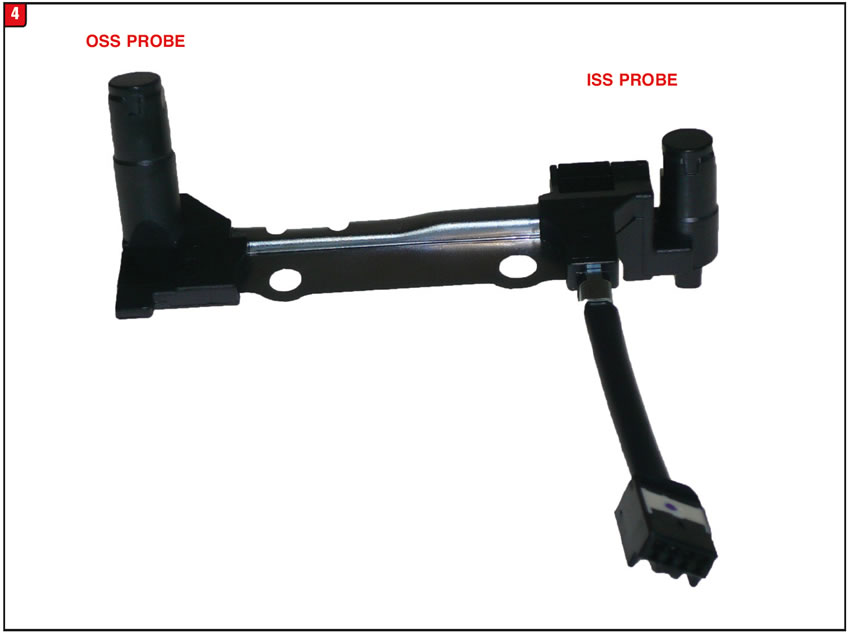
The ISS/OSS sensors are both mounted to a single bracket with one electrical harness and connector (Figure 4). The assembly is bolted to the upper side of the valve body so at least the entire transmission did not have to be removed to gain access to it.
With the valve body out the technician started to look over the sensor assembly to determine what the issue was. Everything appeared to be right and tight including where the harness plugged into the case connector. A resistance check was made to make sure that there were no breaks in the wiring or in the sensors themselves. As a last resort the technician decided to check a fundamental aspect of any speed sensor, which is the airgap, and low and behold something did not measure up.
The airgap between both sensors and the components that trigger them was a bit excessive, by approximately 0.080. Fortunately, the technician kept the original sensor assembly and when he compared it to the replacement assembly everything became clear. Both sensor probes on the brand-new replacement unit were shorter because it was the wrong part(Figure 5).
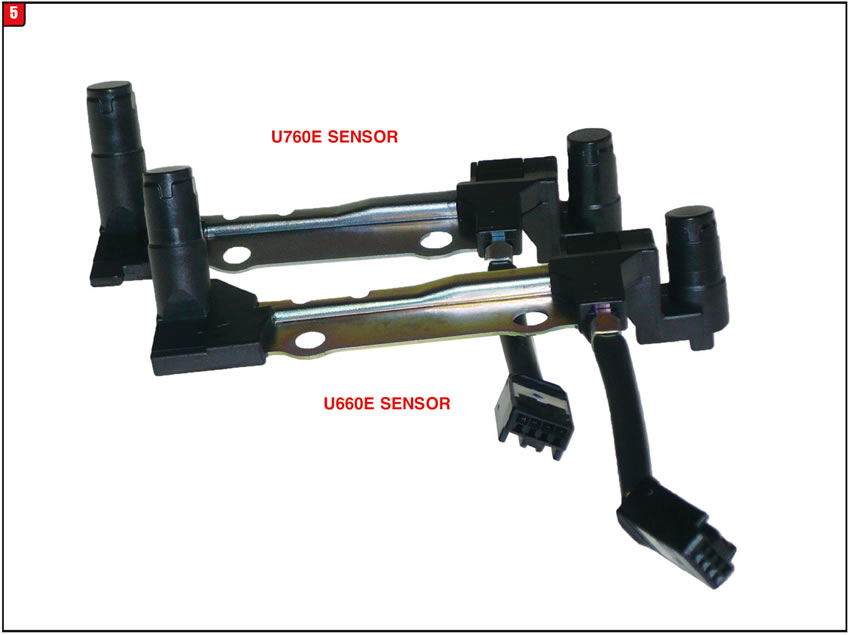
Apparently there was either a disconnect between the requested part by the shop, how the distributor salesperson entered the order or how the item was selected in the warehouse. Regardless, the shop ended up with a sensor assembly for a U660E, which is shorter, instead of a U760E part.
One way to determine the correct sensor is to measure the length of the probes. For instance the OSS probe, which is the longer of the two, will measure approximately 1.055 for the U660E and approximately 1.135 for the U760E. An easier way, however, is to look at the part number, which is molded into the plastic bracket. The U660E part number is 89413–0T010 and the U760E part number is 89413–06010.
The sensor probe that is mounted toward the front of the transmission is the OSS and is triggered by the counter gear, whereas the rear sensor probe is the ISS, which is triggered by the clutch drum. There can actually be two different trouble codes relating to a bad or wrong sensor. P0715 is set by input voltage being out of range and P0717 will be set due to a discrepancy between OSS and ISS rpm’s.
Good intentions aside, always verify the part that is ordered ends up being the one received or wasted time and effort will result.


The owner of a 2003 Dodge Ram 2500 was pulling a trailer loaded with stuff when all of a sudden he heard a noise on the order of a bomb going off. After that, the truck didn’t move too well so it had to be towed into the shop. After the noise and movement conditions were verified, the pan was dropped to see what condition the transmission was in. Although the fluid wasn’t too bad there was certainly debris in the pan so the unit was removed. The transmission was a 48RE and the vehicle had 123,000 miles on it, but at least the engine ran well.
Once the transmission was disassembled, the cause of the problems was found. A bearing let loose in the overdrive section and trashed several items.
After receiving the quote the owner of the truck decided to go ahead with the repair so the work began. In addition to the soft parts needed, the job required several hard parts such as the OD planetary and sun gear, piston housing, roller clutch and even the park rod, due to the swivel ball separating from the rod.
Although it took a couple of days to round up everything, the unit went back together fairly well and along with a new torque converter was reinstalled into the vehicle and oiled up. On the road test the transmission was put through its paces and functioned as intended. The vehicle was then put back on the lift to check for leaks or any other issues. At that point, delivery of the vehicle was in sight. Fortunately however, when the truck was parked outside something a bit odd occurred when the technician placed the transmission into park. As soon as the tech took his foot off the brake, the truck started to roll forward due to being on a slight grade, while making a nasty ratcheting sound. Good thing that no one had contacted the customer yet.
Based upon this latest development, the truck was put back in the air to see what the issue was. After examining everything from the shifting mechanism on down, the pan was pulled to see what was up internally. Everything seemed to be hooked up and functioning correctly, so the next step was to pull the valve body. With the valve body removed, the park pawl and cam were examined and using a screwdriver the park pawl was applied to make sure that everything would work correctly, which it did.
Considering that the parking system on an automatic transmission is not rocket science, the rebuilder started to retrace his steps and remembered that among the other items replaced was the park rod, which is certainly part of the equation. Fortunately, the original rod had not been tossed out so the rebuilder was able to compare it to the replacement. Under a closer examination the rebuilder noticed a difference between both park rods, which prompted him to order a new one from the dealer. As soon as the new rod came in the mystery was solved. The wrong rod had been installed.
The A500 / 518 families of transmissions, which mutated from the TF6 / TF8 models, has experienced similar changes in the design of the parking systems. Although the park system layout was the same between TF6 & TF8, there were subtle differences, especially with park rods (Figure 6). Not only was the configuration (bends) different between the two models, but so was the overall length due to the dimension differences of the main cases. The TF8 rod is approximately 3/16” longer than the TF6. The OE part number for the TF6 rod was 2466906 and for the TF8 Rod was 2426894, although neither rod is available from Chrysler.
The basics of the parking system on the four-speed models are the same as the previous three speed models with one major difference, the length of the park rod. The overall design of the overdrive section of the transmission (extension housing) required that the park rods be substantially longer than the three-speed models. Although the four-speed rods are longer than the three-speed models, there is one characteristic that applies to both designs.
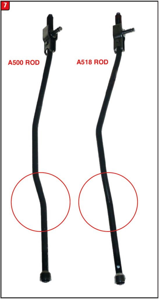
Just as with the three speeds, the rod used in the A500 (42RH/RE) is approximately 8” long, whereas the rod used in A518 models (46/47RH/RE) is approximately 83/16” long (Figure 7). Beyond the length of the rods is the difference in configuration, which is noticeable. The OE part number for the A500 rod is 4431748 and the part number for the A518 rod is 4471478.
In 2003 the 48RE was released for production as a higher capacity transmission overall including the parking system. Although the park rod length and configuration is the same between 46/47 models and the 48RE, there is one noticeable difference between the two, which is the swivel ball on the end (Figure 8A).
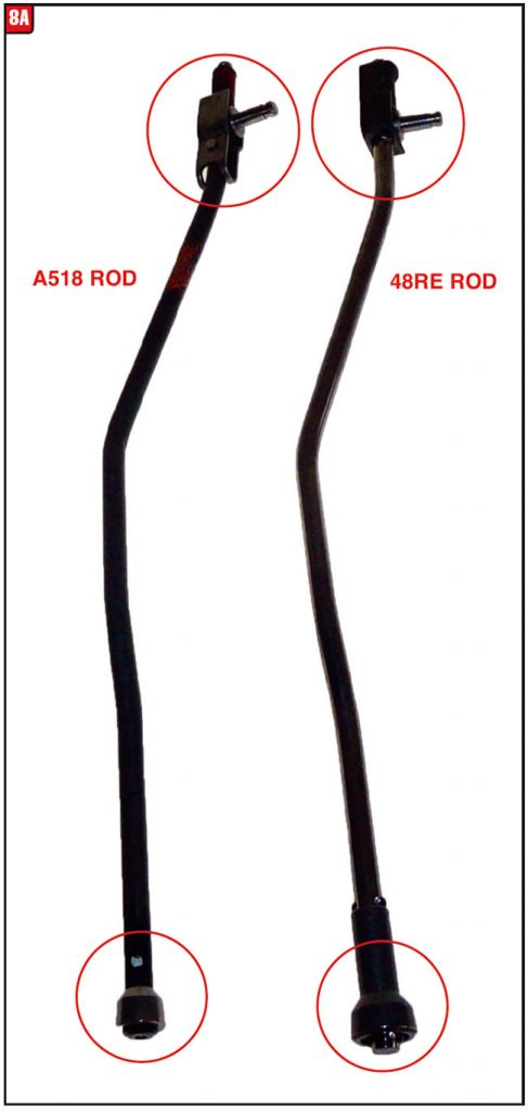
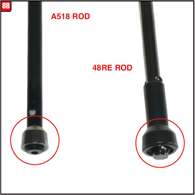
The diameter of the 46/47 model ball is 0.550 whereas the 48RE swivel ball is substantially larger measuring at 0.725 (Figure 8B). The OE part number for the 48RE rod is 52854079AA.
Unfortunately, the rebuilder did not disassembled the transmission initially and did not actually see the original swivel ball that ended up in the trash so the comparison was made with a missing puzzle piece. The missing piece certainly cost everyone extra time and effort. It always pays to have good communication between shop personnel to avoid problems like this.

December 2016 Issue
Volume 33, No. 12
- VW Jetta transmission repair option
- Toyota Camry Self-Inflicted Wound
- Dodge Truck Dilemma – Made Worse


