

Issue Summary:
- The RE4RO1A underwent significant changes in many of the internal parts beginning with the 2001 model year.
- A Toyota/Lexus vehicle may exhibit shift-feel and drivability complaints after the transmission has been overhauled or replaced.
- Failure of the E-clutch piston in ZF 5HP24 (A5S 440Z) transmissions can cause flared 1-2 and 2-3 shifts.
- ZF Industries now offers a valve-body reconditioning kit for the ZF 5HP24.


At the start of production for the 2001 model year, the RE4RO1A underwent significant changes in many of the internal parts, which include the pump and converter and many of the drive and driven components.

These changes were implemented to create a “heavy-duty” version of this transmission to accommodate the more-powerful 3.5-liter engine that the Nissan Pathfinder and Infiniti QX4 were to receive.

Part 1. The light-duty low/reverse-clutch piston is 0.965 inch tall and uses individual return springs and retainer. The heavy-duty low/reverse piston is 0.709 inch tall and uses a return-spring assembly.
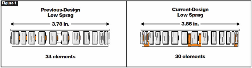
Part 2. The light-duty forward-clutch drum has a 3.78-inch opening for the sprag, which is a 34-element unit (refer to Figure 1), and the low/reverse-clutch lug area is 1.77 inches tall. The heavy-duty forward-clutch drum has a 3.86-inch-diameter opening for the sprag, which is a 30-element unit, and the low/reverse-clutch lug area is 1.65 inches tall.
Part 3. The light-duty overrun-sprag outer race is stamped and has an overall height of 2.382 inches. The heavy-duty overrun-sprag outer race is cast and has an overall height of 2.47 inches.
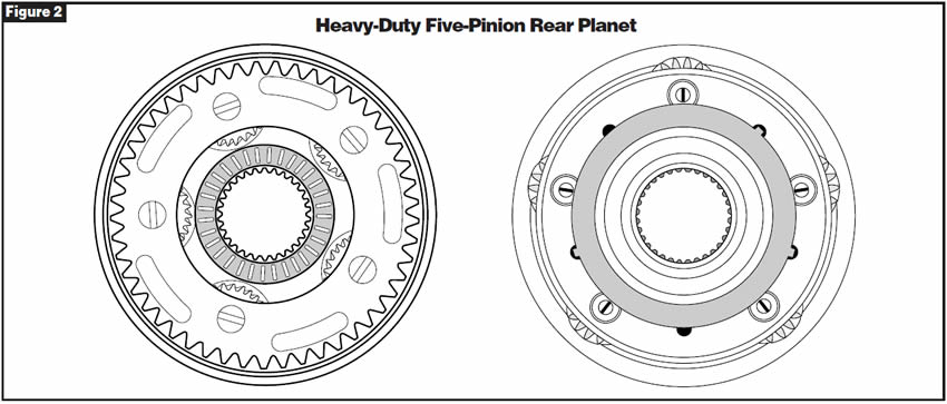
Part 4. The light-duty rear planet is a four-pinion design. The heavy-duty rear planet is a five-pinion design (refer to Figure 2).
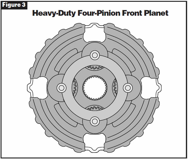
Part 5. The light-duty front planet is a three-pinion design, and the pinions are riveted. The heavy-duty front planet is a four-pinion design, and the pinions are held in by screws (refer to Figure 3).
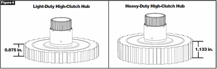
Part 6. The light-duty high-clutch hub is 0.875 inch in overall height (refer to Figure 4). The heavy-duty high-clutch hub is 1.133 inches in overall height (refer to Figure 4).
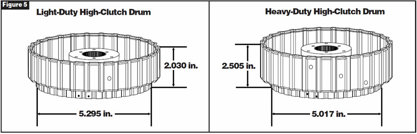
Part 7. The light-duty high-clutch drum is stamped and is 2.030 inches in overall height. It will accept up to four friction plates. The reverse input-clutch hub at the bottom of the drum is 5.295 inches in diameter (refer to Figure 5). The heavy-duty high-clutch drum is a thicker stamping and is 2.505 inches in overall height. It will accept up to five friction plates. The reverse input-clutch hub at the bottom of the drum is 5.017 inches in diameter (refer to Figure 5).
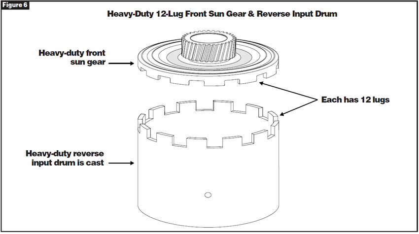
Part 8. The light-duty front sun gear is an eight-lug design. The heavy-duty front sun gear is a 12-lug design (refer to Figure 6).
Part 9. The reverse input-clutch friction plates for both the light-duty and heavy-duty models have 30 teeth. However, the light-duty friction plates have a larger inside diameter than that of the heavy-duty friction plates.
Part 10. The light-duty reverse input-clutch drum is stamped and is 2.559 inches in overall height. The drum has eight lugs to accommodate the eight-lug front sun gear. The heavy-duty reverse input-clutch drum is cast and is 3.011 inches in overall height. The drum has 12 lugs to accommodate the 12-lug front sun gear (refer to Figure 6).
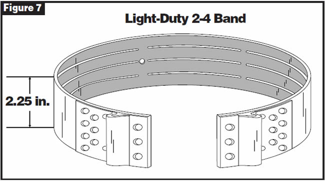
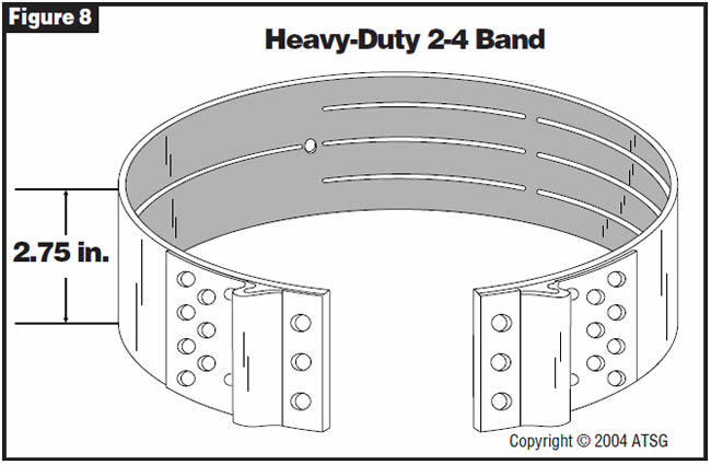
Part 11. The light-duty 2-4 band is 2.250 inches wide (refer to Figure 7). The heavy-duty band is about 2.750 inches wide (refer to Figure 8).
Part 12. A number of the internal bearings have changed from the closed one-piece design to the open two-piece design.

Interchange of all the parts mentioned is possible; however, a great deal of attention must be paid to clearances between all involved components. Take care when exchanging pump assemblies, since some pump covers have provisions for a turbine-speed sensor and some do not. The use of this speed sensor also requires a case that can accommodate the sensor (it has a hole). The input shaft must also have a splined reluctor to excite the turbine-speed sensor, as some do not have these splines.
NOTE: If you put in a pump that has the hole for the turbine-speed sensor without the speed sensor in the hole, a no-move condition will result, because all converter-charge oil will be dumped out of the speed-sensor hole.


The vehicle exhibits shift-feel and drivability complaints after the transmission has been overhauled or replaced.

Cause 1:
Vehicles equipped with fully electronically controlled transmissions require an ECM memory reset to restore the ECM “Relearned Values.”
Cause 2:
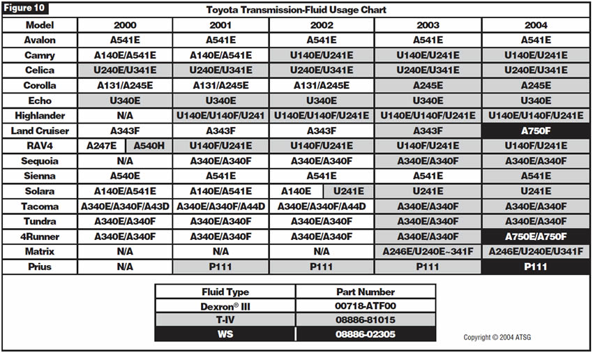
Use of incorrect transmission fluid. Certain transmissions require Toyota T-IV or WS automatic-transmission fluid; others can use Dexron® III.

Correction 1:
The ECM reset procedure for the following vehicles is performed with a capable scan tool only:
- 2000-2003 Echo and Celica
- 2001-2003 Highlander and RAV4
- 2002-2003 Camry
- 2002-2003 Solara with 2AZ engine
- 2003 Matrix
- 2004 Sienna
The ECM reset procedure for the following vehicles can be performed with a capable scan tool or by a manual method:
- 2000 Highlander and RAV4
- 2000-2001 Solara with 5S engine
- 2000-2003 4Runner, Avalon, Corolla, Land Cruiser and Sienna
- 2000-2003 Tacoma and Tacoma Pre-Runner
- 2000-2003 Tundra
- 2001-2003 Sequoia
The manual ECM reset procedure follows:
- Record radio-station presets and #1 driver’s-seat memory position.
- Disconnect the negative battery cable for 5 minutes.
- Reconnect battery cable and reset radio presets and #1 driver’s-seat memory position.
- Start the engine and warm it to normal operating temperature.
- Perform a thorough test drive with several accelerations from a stop with light throttle application until proper transmission shifting is verified.
Note: The following operations may need to be performed:
- Initialize moon roof.
- Initialize power windows
- Calibrate compass.
Procedure for initialization of moon roof:
- Push and hold down the “TILT UP” side of the switch until moon roof tilts all the way up and then tilts down slightly (about 10 millimeters at the rear).
- Check for proper operation of the “One-touch slide open/close” and “One-touch tilt up/down” functions by pushing the switch briefly to the SLIDE OPEN and TILT UP positions.
Procedure for initialization of power windows:
- Turn the ignition switch on.
- Open the driver’s window halfway by pressing the driver’s power-window switch.
- Pull the switch all the way up until the window is fully closed, and continue to hold the switch for 3 seconds.
- Release the switch and check that the “AUTO UP/DOWN” function operates normally.
Procedure for rear-window initialization (SUVs):
- Turn the ignition switch on.
- Open the back door glass fully.
- Press the back-door power-window switch until the window is fully closed, and continue to hold the switch for 1 second or more.
- Check that the AUTO UP/DOWN function operates normally.
Procedure for compass calibration:
- Turn the ignition switch on and check that the Direction N, NE, E, SE, S, SW, W, NW appears on the compass display in the rear-view mirror (pushing the “COMP SWITCH” turns the compass display on and off).
- Push the “MODE SWITCH” for longer than 3 seconds until the zone number (1-15) appears on the display. Then push the switch to select the number of the zone where the vehicle is (see Figure 9).
- Check that the direction N, NE, E, SE, S, SW, W, NW or C appears several seconds after adjustment.
- Start the engine and push the switch for 6 seconds until “C” appears on the display.
- Drive the vehicle at 5 mph, or less, in a circle until the direction is displayed. If there is not enough space to drive in a circle, drive around the block until the direction is displayed.

Important Notes:
- Do NOT perform calibration of the compass in a place where the earth’s magnetic field is subject to interference by artificial magnetic fields such as underground parking, under steel structures, between buildings etc.
- During calibration, do not operate electrical systems such as moon roof, power windows etc., as they may interfere with the calibration.
Use the illustration in Figure 9 for the correct map reference number for compass calibration.
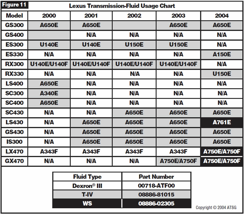
Correction 2:
Some Toyota transmissions require a special type of automatic-transmission fluid. It has been ATSG’s experience that the use of other fluids has caused shift-feel complaints in the transmissions even after the ECM reset has been completed. Use the chart in Figure 10 for Toyota vehicles, and the chart in Figure 11 for Lexus vehicles to determine which fluid should be used in which transmission.


The transmission exhibits flared 1-2 and 2-3 shifts. P0732 and P0733 “Gear Control Malfunction 2nd and 3rd” codes are stored. Disassembly and inspection of the transmission reveal that the E-clutch piston is badly cracked (refer to Figure 12).
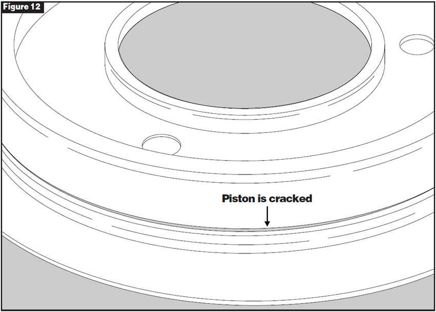
This condition is seen primarily in the Audi A8 and Jaguar XK8/XJ8 models. At this time the cause is unclear; however, it may be non-commanded line-pressure spikes.
Replace the E-clutch piston.

- E-clutch piston . . . . . . . . . . . . . . .1058-375-020

ZF Industries has made available to the aftermarket original-equipment valve-body reconditioning kits. These kits include new valve springs; orifice plugs; small parts, including checkballs; and any other valve updates that have been made. Previously, only two kits were available, for ZF 5HP19 and ZF 5HP30. Now a kit is available for the ZF 5HP24 valve body (see Figure 13).
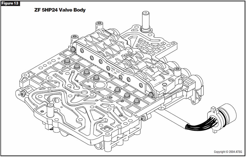
- ZF 5HP24 valve-body reconditioning kit . . . . . . . . . .5HP24VBK
(Note: This kit covers BMW, Jaguar and Rover applications.)

December 2005 Issue
Volume 22, No. 12
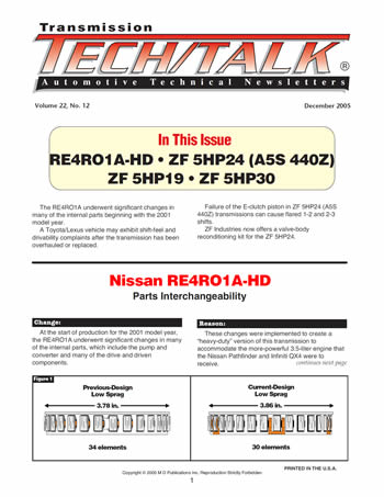
- Nissan RE4RO1A-HD: Parts Interchangeability
- Toyota/Lexus: Shift Complaints After Overhaul
- ZF 5HP24 (A5S 440Z): Failure of E-Clutch Piston
- ZF Industries: Valve-Body Reconditioning Kits


