Technically Speaking
- Author: Wayne Colonna
- Subject Matter: Jatco CVTs
- Issue: Garage shifts
Technical Training
Jatco’s CVT2, CVT7 and CVT8 have their own unique way of controlling garage shifts into gear. Although each of these transmissions utilize a torque converter, great lengths went into designing a strategy that would prevent harsh drive or reverse engagements to prevent damage to the variator (primary and secondary pulley assembly).
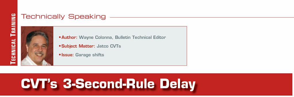
Figure 1 is a hydraulic schematic for the CVT2 transmission commonly referred to as the JF011-E. When looking at the area above the manual valve, each of the reverse clutch and forward clutch-feed circuits have a double check-ball arrangement to assist in a controlled apply and release of the clutch. This is just the beginning of the strategy involved in controlling their application.
Following downward the circuit feeding the manual valve with pressure, you come to the select switching valve. The position of this valve is controlled by the on/off lock-up select switch solenoid. When it is energized, it strokes this valve routing regulated pressure from the select control valve to the manual valve. The select control valve is controlled by the lock-up control solenoid, which is a normally low (N/L) PWM solenoid. You will notice that the pressure coming from this PWM solenoid must pass through the select switching valve before it can influence the select control valve. Once it does, it can regulate the select control valve to supply the manual valve with regulated pressure to be used for a smooth apply as it ramps on the clutch. At its extreme, it can also prevent pressure from reaching the manual valve causing a no move condition.
With PWM solenoid pressure having to pass through the select switch valve, once the transmission is fully engaged into gear, the lock-up select switch solenoid turns off, which causes the select switching valve to close. When this valve closes, two things occur: full line pressure is supplied to the manual valve to keep the forward or reverse clutch applied, and the PWM solenoid pressure is re-routed to the lock-up control valve to control converter clutch apply.
Having the understanding now of how this system functions to control garage shifts into gear, there has been issues of delayed engagements. At one point early on, Nissan published a bulletin (NTB-10-147) that said a 2- to 3-second delay is normal operation. If it was longer, there may be internal transmission issues. A TCM re-flash was also provided in this bulletin to improve the delay.
There have been reports of shops using a slightly lighter weight spring on the select control valve with a degree of success.

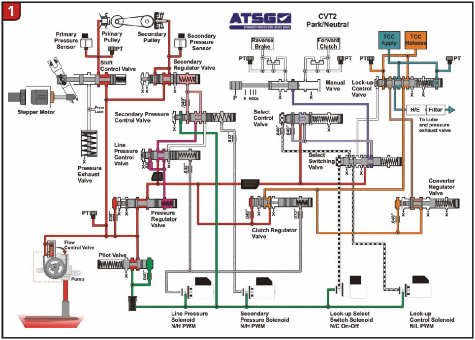
Looking now at the hydraulic for the CVT7 in Figure 2, a completely different approach to controlling a garage shift into gear can be seen. The manual valve is being supplied with pressure from the solenoid regulator valve. This solenoid feed pressure also supplies pressure directly to the solenoid that controls pulley pressure and the solenoid that controls line pressure. It does not directly supply pressure to the low brake solenoid or the high clutch/reverse brake (H&R) solenoid.
Using a drive engagement as an example, when the manual valve is placed into drive, the solenoid feed oil at the manual valve is directly routed to the low brake solenoid. It is also routed to the select relay valve, which strokes and then routes solenoid feed pressure to the H&R solenoid. The low brake solenoid is a PWM solenoid when is then used to ramp the low brake on for a nice garage shift into gear. When the manual valve is placed into reverse, the H&R solenoid (which is also a PWM solenoid) is then used to ramp the reverse brake clutch on for a nice garage shift into gear. This change in control seems to be an improvement thus far when compared to the CVT2.
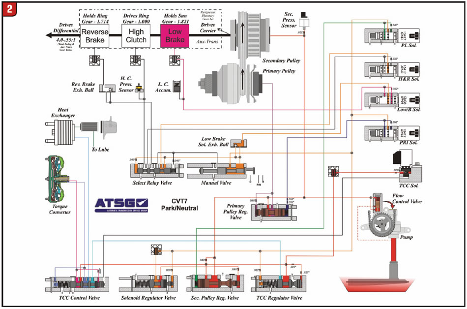
The CVT8 utilizes an aspect of the CVT2 design as well as the CVT7. Looking at the hydraulic for the CVT8 in Figure 3, a double check-ball arrangement can be seen for the reverse clutch circuit and for the forward clutch circuit. This is just like the CVT2 transmission.
What is similar to the CVT7 is that the clutches are engaged via solenoid control with a slight twist in comparison. The CVT8 strictly uses the select solenoid to engage the reverse or forward clutch. The solenoid is supplied with regulating pressure from pilot valve A. This PWM solenoid then supplies pressure directly to the manual valve controlling both a reverse and drive engagement. This solenoid can also prevent any engagements for occurring as a failsafe function or when it malfunctions. But this system does seem to be an improvement in the time it takes to engage the clutch when compared to the CVT2. However, knowing the 3-second-rule delay with the CVT2 transmission, if you experience a garage shift into gear longer than 3 seconds with the CVT7 or 8, you know for sure that you have a problem with the transmission or software.


