Technically Speaking
- Author: Wayne Colonna
- Subject Matter: CVT 7
- Issue: Bore wear
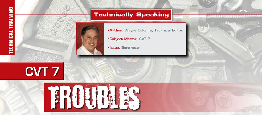
The CVT 7 used in Mitsubishi and Nissan vehicles (Figure 1) is unique in that between the pulley assembly and the differential is a planetary gear set controlled by a reverse brake, a low brake and a high clutch.
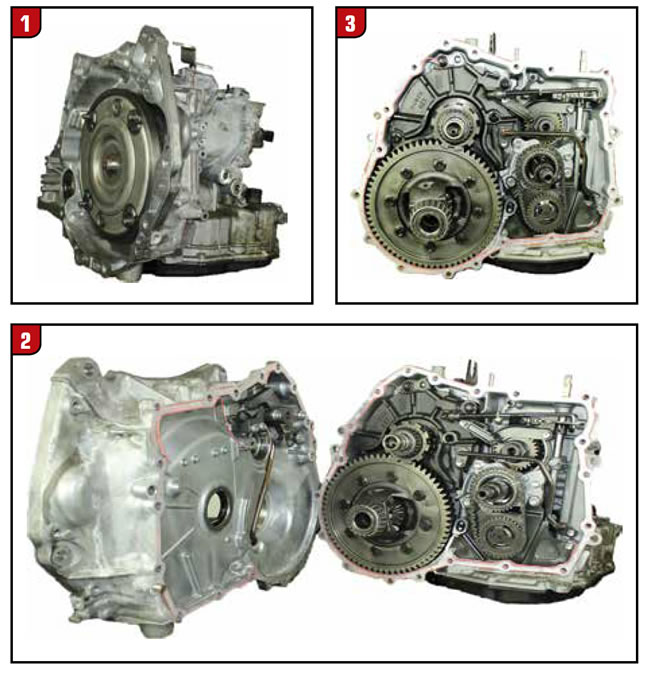
When the converter housing is separated from the main case (figures 2 and 3), it can be seen that the torque converter drives the input shaft, which in turn directly drives the primary pulley.
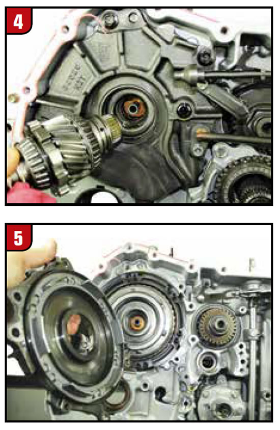
The park gear also consists of an output gear, which drives the differential (Figure 5). The output and park gear is splined to the planetary gear set, which is driven by the secondary pulley.
What does this all mean? At launch in drive, the pulleys are in a low ratio wrap. With the low brake applied, power flow is connected to the differential, which in turn moves the vehicle forward. The pulleys remain in a low ratio wrap. When the vehicle reaches an engine RPM that would require a shift, the low brake is released while the high clutch applies. A literal 1-2 shift took place. Afterward, the pulleys begin to ratio.
When the park and output gear cover is removed, the reverse brake piston comes with it (Figure 6). When the reverse brake return spring, wave plate, steel and friction plates are removed, the high-clutch drum assembly can be removed.
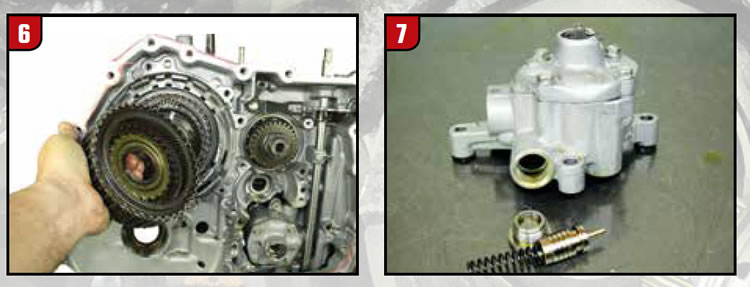
This drum assembly uses a molded piston to clamp down on the stack-up. It is this molded piston that gets compromised causing a flare on the shift both up and down. But it also can cause ratio errors as the pulley ratios from a low ratio wrap to a high ratio wrap. It simulates a slipping pulley or pump volume problem. This can be very misleading causing a great deal of time chasing after pulley issues or pump/filter issues. In fact, the pump has the same problem as the CVT 2. There is a volume control valve inside the pump that wears the bore (Figure 7). This is a problem area and should always be looked at. But it’s also a reason why the molded high clutch piston is often not considered.
As far as the pulleys having pressure issues, the secondary pulley regulator valve is notorious for wearing out the bore in the valve body causing pressure loss (Figure 8). However, if the volume control valve bore in the pump is not worn and this secondary pulley regulator valve bore is also not worn, check the high clutch molded piston and sealing rings for any ratio errors you may have.
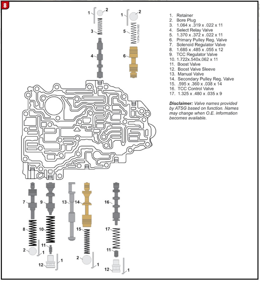
Back to bore wear: while into the valve body, inspect the TCC regulator valve bore. It too is a high bore wear area affecting the operation of this transmission.
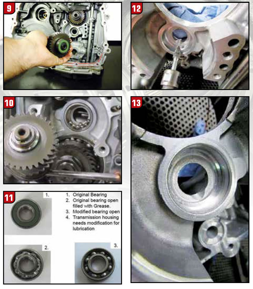
Another common problem to contend with is the input shaft’s ball bearing comes apart (Figure 9). Leo Spaargaren from Automatic Choice in the Netherlands sent to me figures 10 through 13 showing modifications they make to keep the bearing from failing again after it’s replaced. The replacement bearing they use is an open face bearing type. They “dremmel” a notch into the bearing pocket allowing more splash oil to get into the bearing, keeping it cool and lubricated. Sometimes the bearing fails so terribly the bearing pocket in the case gets torn up or wallowed out. A replacement case will be needed unless you have the means to get it machined and sleeved.
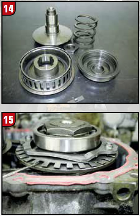
Another issue that comes up is the speed sensor “basket” ring on the secondary pulley comes loose (Figure 14). This can easily be fixed by re-fastening it with spot welding. The last item is a self-inflicted issue. The primary pulley speed sensor exciter ring (finger-type) bends just looking at it (Figure 15). These fingers are so thin, it doesn’t take any effort for them to bend causing an air gap issue. Be very careful handing the primary pulley especially when inspecting the internal parts for wear.


