
Up to Standards
- Subject: Causes of common driveline failures
- Units: NV 271, 273, 246; Tremec 3650; BW 4473, 4476, 4481, 4482, 4484, 4486, 4494, 4495
- Essential Reading: Rebuilder, Diagnostician
- Author: Mike Weinberg, Rockland Standard Gear, Contributing Editor
We have learned over the years that all mechanical designs have some inherent defects. If you take apart 20 of the same units, you will usually find that they failed in the same place. Sometimes the cause is a part that can be made heavier-duty; occasionally you will find that certain parts have less longevity than others, and sometimes the root cause of the failure is outside of the unit.
We must never lose sight of the basics of modern vehicle technology and design encompassing a wide variety of complex systems that activate and control the functions of the major components we are working on. The following are some examples of common failures that generate a lot of traffic on the hotlines and have many technicians scratching their heads and wasting time and money. One thing we know from experience is that you are only as good as the last thing you did for a customer.
New Venture 271 and 273 transfer case: catastrophic failures
In the 1999 model year Ford Motor Co. started to use the NV 271 and 273 transfer cases in its F-250 and F-350 models. These units are the same design, with the 271 being shifted manually and the 273 shifted electronically. As to be expected these pickups are big and heavy-duty, and the transfer cases are likewise. When you pick up one of these units you will discover how big and heavy they really are.
Designed for maximum loads and torque application, these units have a high rate of catastrophic failures, in which they come into the shop literally cracked in half. This is an expensive repair and one that will not last long unless you find the root cause of the problem. The issue is not in the transfer-case design or manufacture, but in parts outside the unit – specifically the driveshafts, usually the front one.
The front shaft is designed with a double Cardan joint (figures 1 and 2), or the earliest design of a CV-like joint.
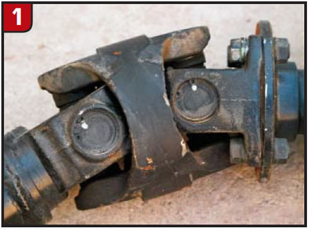
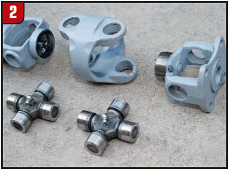
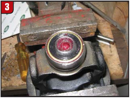
There are two U-joints in the same housing with a centering ball (Figure 3) between them.
Some varieties of rear driveshafts also have a double Cardan joint. If the centering ball between the U-joints breaks or is out of line, the joints go out of phase and are no longer centered, putting a tremendous stress load on the transfer case and causing an early death. If you are replacing U-joints on one of the driveshafts you must be careful not to push the U-joint far enough to damage the centering ball, as it cannot be repaired. If a shaft has a damaged center ball, it must be replaced completely.
One would think this condition would produce a noticeable vibration, but apparently some people keep driving until they need a driveshaft and a transfer case. Whenever inspecting one of these vehicles, look at all the components involved in the transfer of power, as just replacing the transfer case will lead you back to square one.

New Venture 246 neutralizes during driving
The New Venture 246 is used in a wide variety of GM pickups, cross-over vehicles and SUVs. It is a computer-controlled, clutch-applied transfer case equipped with an encoder motor that shifts the unit into various ranges and modes and applies the internal clutch pack to send power to the front wheels when needed.
In 2003 the transfer case was redesigned, and the detent assembly that held the sector shaft in a particular gear was eliminated. The encoder motor has an internal motor brake that is applied when the motor has selected the position the driver chose. When the computer sees a request for a gear selection, it releases the brake and the transfer-case sector shaft moves to the correct position. Upon completion of the shift, the encoder-motor brake is reapplied to hold the gear selection until the driver makes another choice.
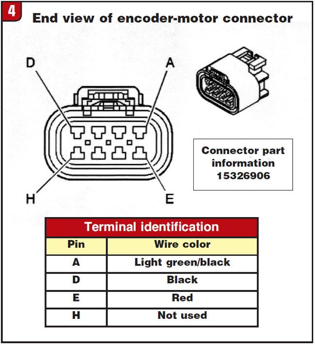
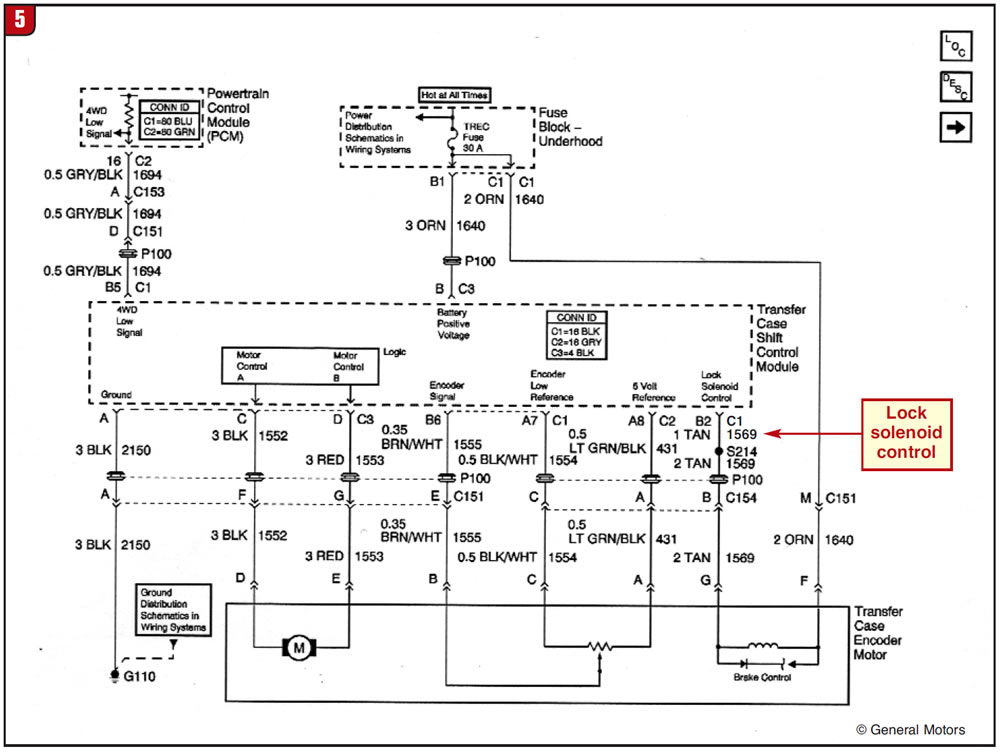
If you take off one of these motors for service and the transfer case is not in the same position as it was when the motor was removed, the motor will not reinstall unless you move the sector shaft or use a 9-volt battery to power the tan wire (circuit 1569) on the motor (figures 4 and 5). When you apply nine volts to the motor you will hear an audible click, which is the motor brake releasing, and you now can turn the motor shaft to the correct position.
You must be careful not to turn the motor too far in either direction unless you wish to buy another motor. The encoder-motor brake can fail or there can be some electronic problem with circuit 1569 and the brake will be inoperative. The usual complaint is that the vehicle went into a neutral position in the transfer case. Pushing the A4WD control button will regain power flow for a time until the sector shaft moves on its own because of the lack of a detent to hold it in place. Again, the problem is outside the transfer case in the control system. If you are not looking at the whole picture and not thinking outside the box you will have many long days and no good results.
Clutch-release issues
The single greatest cause of manual-transmission shift complaints and failures is a bad clutch release. The slave cylinder or cable must be capable of depressing the fingers on the pressure plate far enough to release the disc from the flywheel and the pressure plate. The disc should have an average of 0.050-inch air gap from the pressure plate and the flywheel to disconnect the power flow from the engine to the transmission. If this does not occur, the synchronizer rings and shift forks have to fight the torque load from the engine, and they are not equipped to do so.
Causes of improper clutch release include bent or deflected clutch pedals, stretched cables, worn clutch forks, bad pressure plates, excessive crank endplay in the engine, air in hydraulic lines, a bad master or slave cylinder, and mismatched clutch components. We have even seen a customer who was 4 feet, 6 inches and could not reach the pedal to fully depress it and release the clutch.
Be particularly careful with aftermarket clutches that the customer had installed or wants installed. You need to measure the travel of the release bearing on the slave cylinder (concentric slave) to the pressure-plate diaphragm fingers to make sure it is enough to release the pressure-plate clamp load fully. There are dozens of aftermarket clutch manufacturers that produce a good product, but once you vary from the stock components you may have to shim the concentric slave forward to get a good release and prevent notchy, stiff shifts and transmission damage. This will be particularly true on high-horsepower applications on sports cars and with dual- or triple-disc setups. The customer may know where he wants to go but maybe not how to get there. A quick test to determine whether the clutch release is the problem is to jack the drive wheels off the floor and run the car through the gears. If it shifts well with no load on the drive wheels the problem is related to clutch release.
Fluids and fluid levels
Once upon a time when life was simple we needed a few different types of fluid. Today, as you know, fluid type and quantity are very transmission specific. Manual-transmission and transfer-case fluids are designed to lubricate and have a specific coefficient of friction to work correctly with the synchronizer and clutch materials found in the unit. It is very easy to undo all the care that went into a good, by-the-book rebuild of a unit by using an incorrect fluid.
That said, some other areas regarding fluid quantity need to be addressed. Too much fluid in a unit can create higher transmission operating temperatures and poor shift quality. The Tremec 3650 five-speed used in Ford Mustangs is an example. If you “fill to spill” on this unit it will not work correctly. It should be filled to 1/2 inch below the bottom of the fill plug bore. That extra 1/2 inch of fluid will alter the synchronizer timing, as the gears running through the oil create a windage situation. When the throttle is released to make a shift, the fluid slows the rotation of the gear train too quickly and the synchronizers have to work harder to match shaft speeds, causing notchy shifts and customer complaints.
Going in the other direction, certain designs have placed the fill plug too low and the unit is under-filled with fluid right from the factory. Many early models of BorgWarner transfer cases used in GM vehicles (4473,4476, 4481, 4482, 4484, 4486, 4494, 4495) had the fill plug placed too low, and even when filled to spill the unit was still a quart short of fluid. The fix here is to fill to spill and then, after replacing the fill plug in the transfer case, remove the speed sensor on the extension housing and add one more quart of fluid through the speed-sensor hole. To the best of my knowledge replacement case halves and later production units have been supplied with a fill plug in the proper location, but some early models are still on the road. Failure to check on something this simple causes an expensive failure.
All the conditions mentioned are real-world problems that show up every day on technical hotlines. Ignorance is not bliss; it is expensive.