
TASC Force Tips
- Author: Gregg Nader, Sonnax Technical Center
Watch out when swapping stator shafts from one pump cover to another on 700-R4/4L60-E transmissions. We have all been there before. You have a unit with a good pump cover and a damaged stator shaft, and in your pile of parts there is a good stator shaft in a damaged pump cover. All you need to do is press the good stator shaft into the good pump cover and you will have what you need to get this car down the road today. Sounds simple, but how often are things that simple in this business?
Anyone who has tried this knows how difficult it can be to align the hole in the stator shaft with the pin in the pump cover. The reason is that when these parts are manufactured the alignment pinhole is “drilled in assembly.” That means that after the stator shaft and pump cover are assembled and bolted together, the alignment pinhole is drilled into the stator and pump cover. Finally, the pin is installed and staked in place.
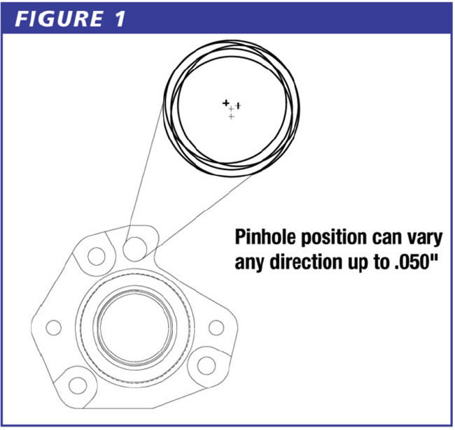
The problem is, the alignment pinhole is not always drilled in exactly the same spot. The center point of the alignment pin varies from one unit to another by as much as 0.050 inch (see Figure 1)!
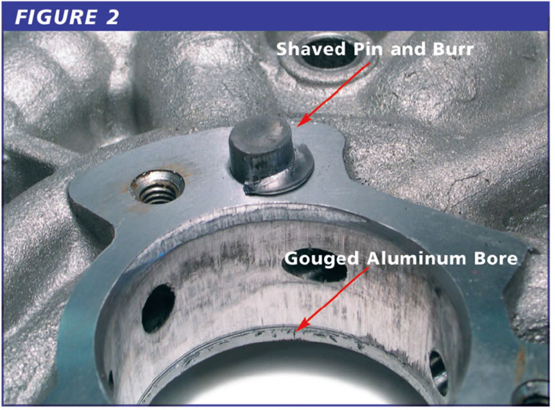
This creates problems when you’re swapping parts. Often the hole in the pump cover and the hole in the stator shaft are close, but not exactly the same as the original parts. In this case, just being close is not good enough and can cause real problems. When you press the parts together, the stator can shave the side of the pin, creating burrs that become trapped between the pump cover and stator flange. This causes misalignment of the stator shaft and also causes the stator shaft to tilt as it is being pressed in. When the stator shaft tilts, the leading edge of the stator will gouge the aluminum pump-cover bore, leading to cross leaks and loss of oil pressure.
Figure 2 shows what can happen when these parts are pressed together. These problems often go unnoticed when the parts are being assembled in a press. The assembler did not feel the metal being shaved off the pin or the aluminum being scraped from the pump-cover bore. This happened even though the bolt holes in the stator and the threaded holes in the pump cover lined up perfectly. This unit was plagued by low pressure and converter concerns after overhaul.
A better way to assemble these parts is to do it as GM does, installing the pin after the parts have been assembled. Use three threaded alignment pins to guide the stator into place. Make sure the chamfer on the leading edge of the stator shaft is not sharp and will not cut into the aluminum pump cover. Heating the pump cover in a cleaning machine will make it easier for the stator shaft to press in and minimize the chance of the stator shaft gouging the aluminum pump cover.
Once the stator shaft is installed and bolted in place, inspect the pinhole for misalignment. If the misalignment is minimal, a 7⁄16-inch drill bit and 7⁄16-inch-diameter pin will work. If the misalignment is severe, a 1⁄2-inch bit and 1⁄2-inch-diameter pin are required.
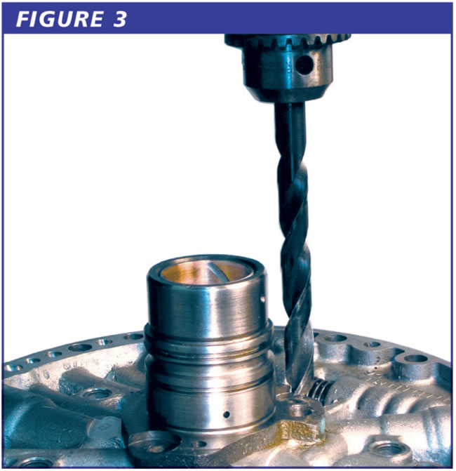
Oversized pins can be cut to 3⁄4-inch lengths from drill blanks or steel rod. Mount the pump cover/stator to a drill press and carefully drill the pinhole oversized (see Figure 3). Clean the hole, then coat the hole and oversized pin with Loctite 609 sleeve-retaining compound (or equivalent). Tap the oversized pin into the hole and stake in place.
Aftermarket stator shafts have features that the original shafts do not include. Most aftermarket stator shafts accommodate different pin locations with elongated bolt and pin holes. This style does not require oversized pins.
The TASC Force (Technical Automotive Specialties Committee) is a group of recognized industry technical specialists, transmission rebuilders and Sonnax Industries Inc. technicians.


