Technically Speaking
Subject: Addition of variable line-pressure-control solenoid
Unit: 41TE/41TES, 42RLE
Essential Reading: Rebuilder, Diagnostician
Author: Wayne Colonna, ATSG, Transmission Digest Technical Editor
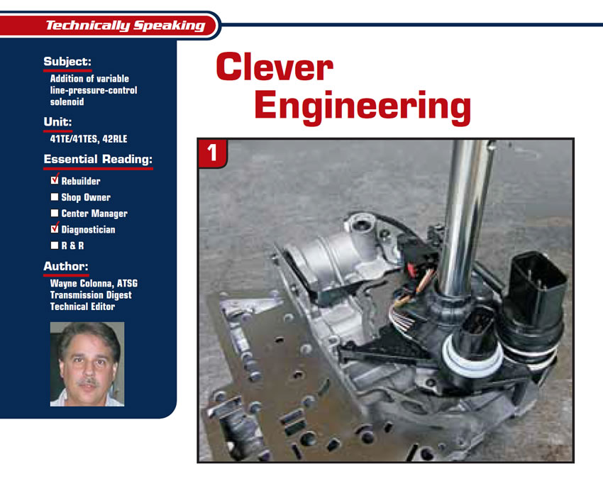
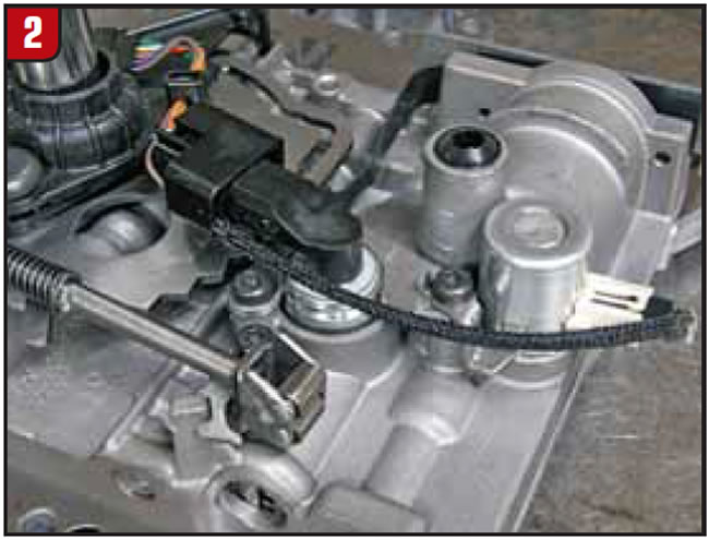
Starting with the 42RLE in 2005, followed by the 41TE in 2007, the engineers cleverly redesigned the valve body to accommodate a variable line-pressure-control solenoid and transducer. Figures 1 and 2 show how these additional components are situated on the valve body with the 41TE transmission. This also required an additional pass-through case connector, resulting in changes to the case as well.
The main purpose for the addition of this variable line-pressure-control solenoid is not to increase line pressure but rather to decrease it. The 41TE, 42RLE and even the 42LE have always been designed to provide three predetermined line-pressure levels. If you think about it, they never had a pressure-control solenoid, throttle cable or a modulator to regulate line pressure. The pressure levels were controlled by the internal design of the valve body; the hydraulics themselves provided about 120-145 psi in Park, Neutral and any Drive-range 1st and 2nd gears. When a shift into third took place, overdrive-clutch oil was sent to the pressure-regulator valve to do a pressure cutback, providing about 75-95 psi in third and fourth gears. When the selector lever was placed into reverse, the manual valve routed oil to the pressure-regulator valve to boost line pressure to about 175-235 psi. It was then up to the computer to pulse-width modulate the solenoids for a controlled garage shift into gear and for shift transitions.
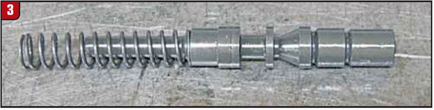
With the change made to the 41TE and the 42RLE by the addition of a pressure-control solenoid, the pressure-regulator valve was changed from a multi-piece valve to a single valve (see Figure 3). There are now two predetermined pressure levels in terms of maximum pressure. In reverse there can be a maximum of 250 psi, and in any drive range in any gear you can observe a maximum of 150 psi. But with the line-pressure-control solenoid, line pressure can be regulated down to as low as 35 psi in any drive range and 58 psi in reverse.
One main reason for this is to provide low line pressure while the vehicle is idling in drive or reverse to reduce engine effort in turning the pump, for the sole purpose of increasing fuel economy. Line pressure also can be decrease during low torque demands for the same reason.
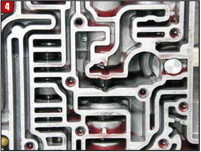
So how did the engineers manage to take an existing design and poke into the valve body a solenoid and transducer? Figures 4 and 5 show how the solenoid and transducer protrude into the casting right where the main line pressure is regulated at the pressure-regulator valve.
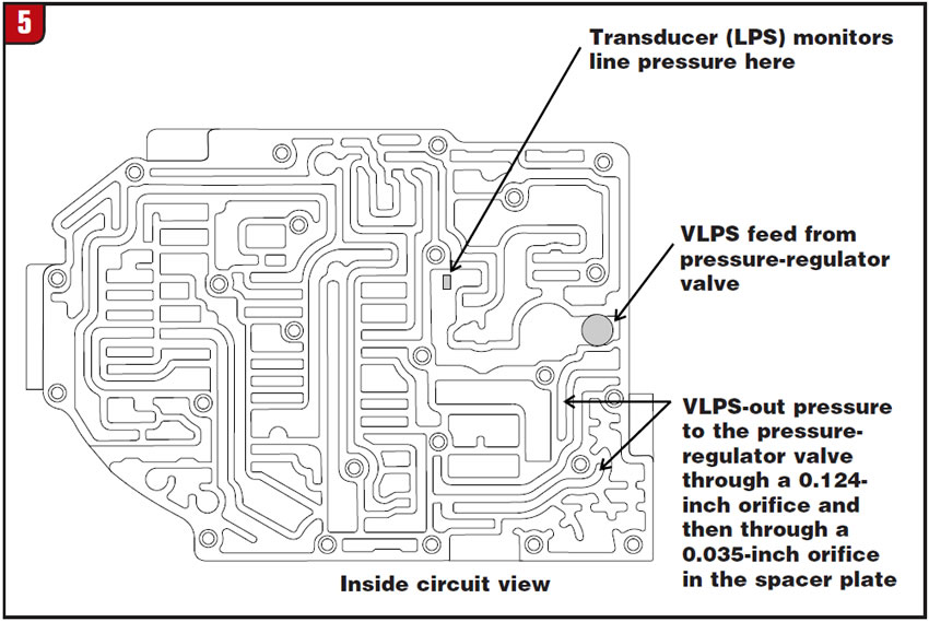
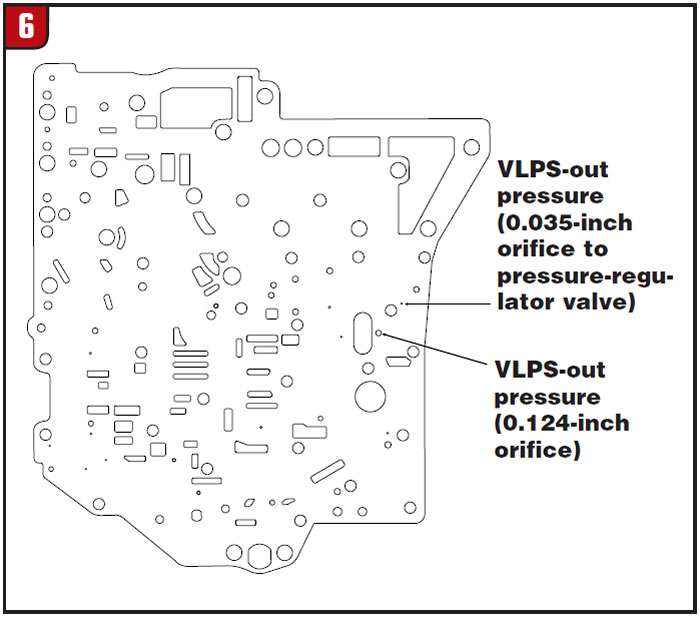
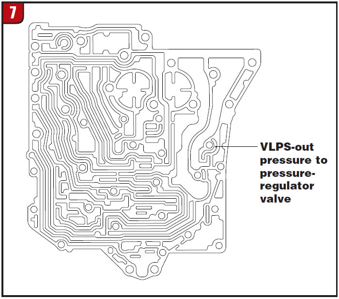
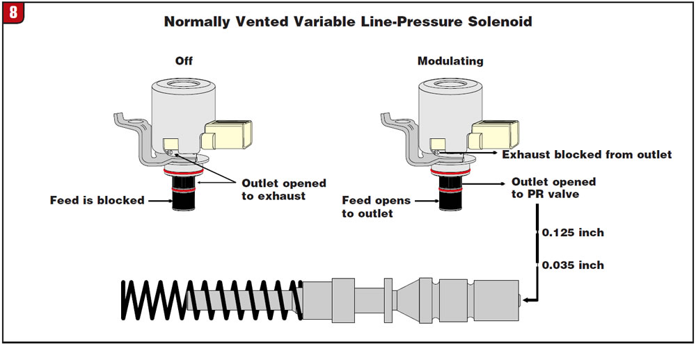
When the variable line-pressure-control solenoid is off, maximum line pressure occurs. But when the solenoid is modulated, the solenoid routes regulated oil from the main line-pressure circuit through two orifices in the spacer plate via the channel plate to the top end of the pressure-regulator valve, as illustrated in figures 6, 7 and 8. The higher the on time of the solenoid the lower the line pressure becomes. A very clever fitting by the engineers, I think.
This new-design 41TE is now referred to as the 41TES, and from what I have been told it will be used in these cars:
- 2007 and up Chrysler Sebring 2.4- and 2.7-liter
- 2008 and up Dodge Avenger SE, SXT 2.4- and 2.7-liter
- 2009 and up Dodge Journey 2.4-liter.
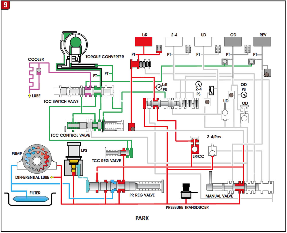
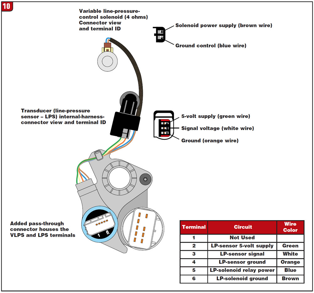
Figure 9 is a complete hydraulic schematic in the Park position at idle for a fuller view of the solenoid and transducer’s environment. Figure 10 provides pin functions for the new pass-through connector and identification of internal-connector terminals for any needed diagnostics.
Thanks to the good folks at Whatever It Takes Transmission Parts for the 41TES valve body.


