Tech to Tech
- Subject: Transmission in limp mode after overhaul
- Vehicle Application: 1995 Dodge Intrepid
- Essential Reading: Rebuilder, Diagnostician, R & R
- Author: Jeff Bach
Dodge Intrepid’s limp mode gets complicated, but Jeff is ‘grinnin’ like a puppy draggin’ a broken leash’
Chrysler transmissions have been difficult to diagnose for technicians since the beginning of electronic shift solenoids.
They use a separate transmission-control computer that is sometimes hard to read.
The biggest problem is that to get all the data and output functions of the transmission controller, you need a Chrysler DRB 3 scan tool, which is not a widespread tool in the independent automotive-service industry. The other problem is that most general-repair shops don’t do automatic transmissions, so that leaves the diagnostics up to the very few transmission shops that can justify the expense of a DRB 3. Some aftermarket scan tools will at least read codes from the transmission controller (or trans controller).
Solenoid packs, input-shaft speed sensors, output-shaft speed sensors and VSS sensors are all common issues – as are the trans controllers and wiring. With this many problem areas that can affect the transmission operation externally, you can imagine what a transmission shop goes through when there is still a problem after they do a complete overhaul on one of these early Chrysler products.
I just finished a 1995 Dodge Intrepid that had had a recent transmission overhaul with a rebuilt transmission control module (TCM) and came back in, in limp mode. I got the car from another repair shop that was looking at it for the transmission shop.
The repair shop had the ability to read the codes with its aftermarket scan tool, which pointed the shop in the direction of the solenoid pack. The shop’s technicians replaced the solenoids and got the same problem right back before getting out of the parking lot. They still had a solenoid code and the trans was still in limp mode.
Next step: Replace the solenoid pack again. It’s still stuck in limp mode with the same code they sent to me to trace the wiring problem, so that must be it.
I haven’t replaced my DRB 3 (it has a small crack in the bottom right corner of the face) since a robbery a year ago, so I’m doing all my testing with the wiring diagram taking voltage readings and scope waveforms at the TCM connector. This is my favorite way to trace these kinds of issues anyway. I start with the assurance that all the power circuits and grounds are intact.
From there, I check that the input- and output-speed-sensor signals are good. After assuring myself of the integrity of these signals, I move on to the four MVLPS (manual valve lever position sensor) circuits so I can be sure the TCM sees the correct gear range. I’ve had issues with these signals before. If you don’t have the ability to see these inputs on a scan tool, the easiest way is to make a small graph on a notepad and put a column under each of the P, R, N, D, 3, L circuits. Next, record the voltage reading for each of the four circuits as you shift through the gears.
The pins at the TCM were numbers 1, 3, 41 and 42. When the chart is through, if the voltages are all correct, you will see a pattern. Three of the four readings in each column should have the same voltage, either three near ground and one near battery voltage or vice versa. You don’t need a chart to compare them with.
The MVLPS circuits all checked out OK. I went next to the four solenoid circuits to see whether they all read battery voltage. With the key on, power is fed to the solenoid pack through the coils of each solenoid, then to the TCM, where it controls the solenoids’ ground circuits to operate them. All four showed battery voltage, which seemed to verify the circuitry. My next test was going to be a test drive with the scope hooked up, monitoring the current for each solenoid, to see whether the circuits remained intact under load.
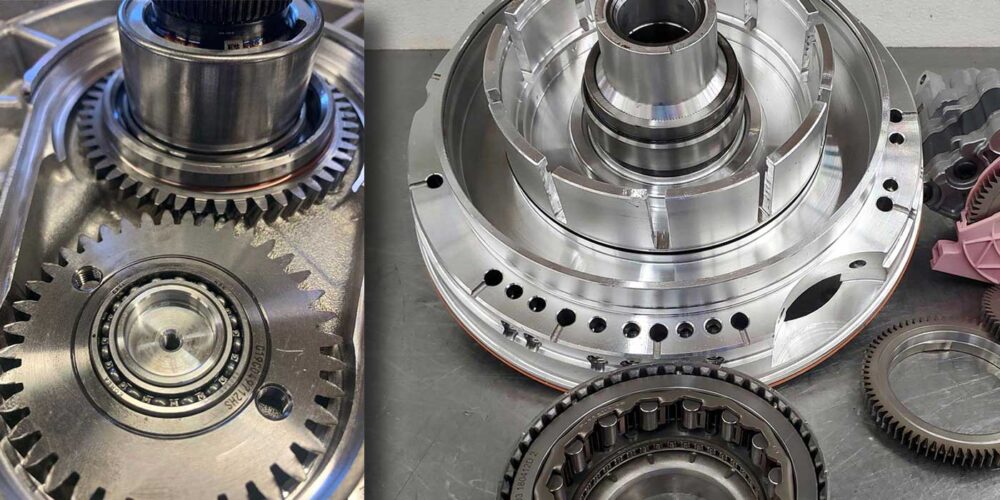
The thought came to me that the TCM saw the problem right away, so it must be doing its own current-flow validity test, perhaps even at key on. I connected my current probe to the scope and grabbed the first circuit at pin 19, the 2-4 solenoid control.

Figure 1 shows the result at key on.
Now, this always tickles me to see. The significance of this pulse is manifold. The first is confirmation that the TCM is self-testing the solenoids before the car is even put in gear. This saves a lot of scoping and driving time. Next, it lets me see what the PCM sees when it goes into limp mode and sets the code. The last thing is, I don’t even have to know what a spec is for this test pulse. I just need to see that all the solenoids have the same waveform.
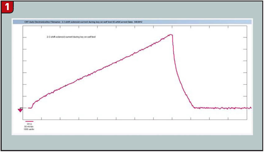
I moved the current probe to the next circuit, pin 20 (the LR solenoid), and got Figure 2.
I like it so far. Next, I grab pin 59 (the UD solenoid), which looked identical to the other two.
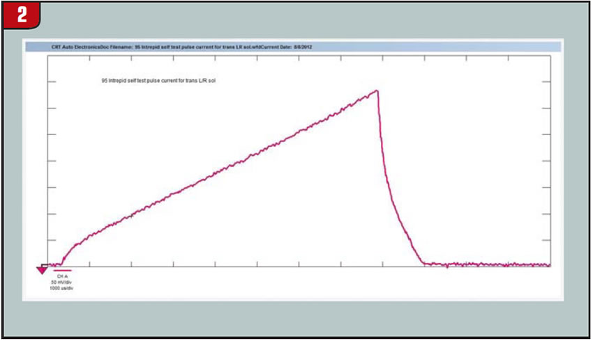
The neat part about these circuits is that pins 19, 20, 59 and 60 are all four together at the end of the TCM in two separate rows. The final circuit was the OD solenoid at pin 60.
I couldn’t even get this circuit to trigger at these settings, so I had to change to a lower scale on the probe, which yielded the waveform shown in Figure 3.
Finally, a “yahoo” moment. My friend Duane stopped by at this moment and asked me, “What did you just do? You’re grinnin’ like a puppy draggin’ a broken leash.” My next test was to grab all four circuits in the probe at once and change the time base on the scope to show all the solenoids in successive order for comparison.
Figure 4 gives me another smile and produces what I like to call a “Sesame Street” moment. “Know what that is?” I ask Duane.
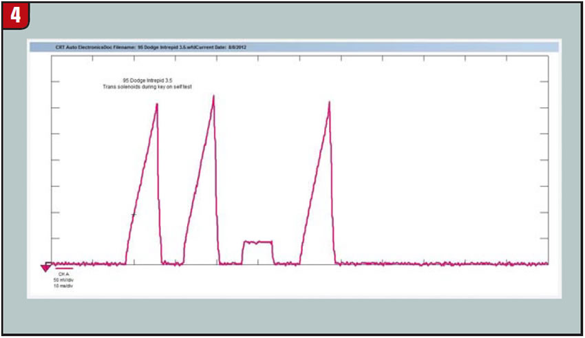
“Sure do,” he replies. “That sticks out like a carrot in a corn crib. Somebody cut down one of your Christmas trees.”
“The computer is seeing the same thing we’re seeing and setting a code for it,” I say.
“Is that the Christmas tree stump code?” he facetiously asks.
“Close enough,” I say.
Next, I take a voltage-signal waveform with the current wave to make sure I’m not up against a voltage drop under load.
Shown in Figure 5 is proof that the problem is internal to the TCM.
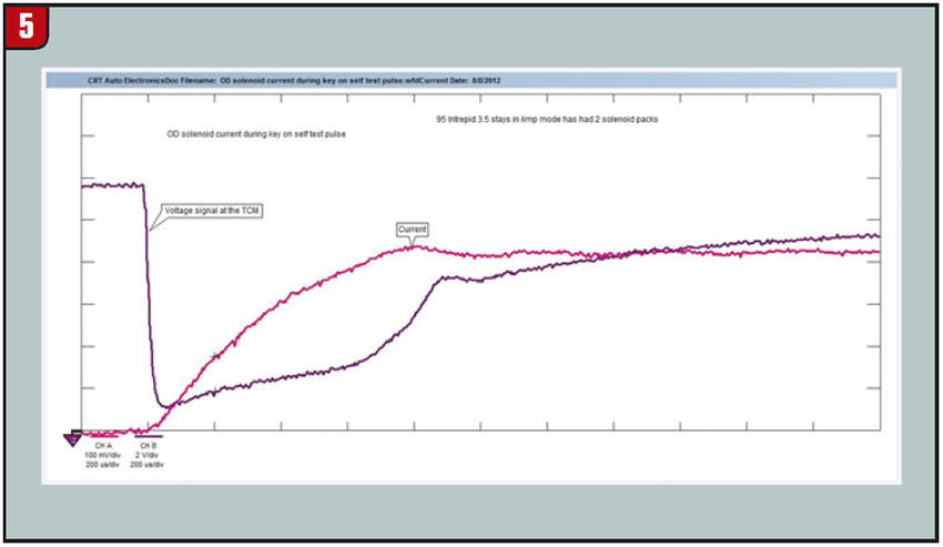
This picture indicates that the voltage is drifting up as the TCM tries to ground it – because of either an internal circuit resistance problem or a bad driver for the solenoid. It also shows that it’s not a problem with a shorted solenoid, as the current pattern doesn’t raise any more sharply than the other ones. I replaced the TCM with a good used one.
Figure 6 tells me that the Christmas-tree patch is back to a full row.
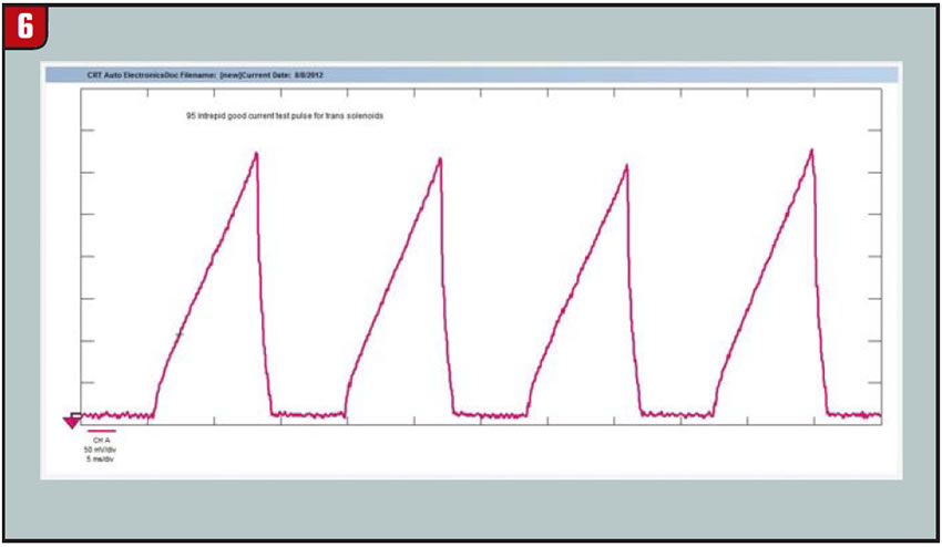
I’ve learned enough from this job to realize that I can get this picture from most Chryslers and know – in under 10 minutes, without a diagram – a whole lot about the solenoids and the trans electrical-circuit integrity. I’m still having as much fun as a puppy on the loose.
Jeff Bach is the owner of CRT Auto Electronics in Batavia, Ohio. You can reach him at [email protected].
This copyrighted article is reprinted with the permission of AutoInc., the official publication of the Automotive Service Association (ASA). To learn more about ASA and its commitment to independent automotive-service and repair professionals, visit www.ASAshop.org or call 800-272-7467.