Chasing Bearing Noise in the JF011E CVT - Transmission Digest

Chasing Bearing Noise in the JF011E CVT

Bearing noises can be difficult to track down even in familiar transmissions which we work on daily. The advantage of the familiar is that we know how to take these units apart and have a general idea of power flow and overall operation–plus, we typically have plenty of extra pieces on the shelf should we need them. Bearing noises in the CVT transmission are much harder to deal with, because we’re not as familiar with it as the units rolling in the door on a daily basis and spare CVT pieces are pretty much non-existent. This has created some minor paranoia when it comes to taking on a CVT repair. Hopefully this article will dispel a bit of the apprehension regarding these units and prove that–with the right tools and a little know-how–CVTs can be repaired and become decent money makers for a shop.

Chasing Bearing Noise in the JF011E CVT

TASC Force Tips

Author: Jim Dial, Sonnax Engineering and Technical Services
Subject Matter: Diagnostics
Unit:	JF011E CVT
Vehicle Application: Renault, Mitsubishi, Suzuki
Issue: Bearing Noise

TASC Force Tips

  • Author: Jim Dial, Sonnax Engineering and Technical Services
  • Subject Matter: Diagnostics
  • Unit: JF011E CVT
  • Vehicle Application: Renault, Mitsubishi, Suzuki
  • Issue: Bearing Noise

Bearing noises can be difficult to track down even in familiar transmissions which we work on daily. The advantage of the familiar is that we know how to take these units apart and have a general idea of power flow and overall operation–plus, we typically have plenty of extra pieces on the shelf should we need them. Bearing noises in the CVT transmission are much harder to deal with, because we’re not as familiar with it as the units rolling in the door on a daily basis and spare CVT pieces are pretty much non-existent. This has created some minor paranoia when it comes to taking on a CVT repair. Hopefully this article will dispel a bit of the apprehension regarding these units and prove that–with the right tools and a little know-how–CVTs can be repaired and become decent money makers for a shop.

The most common abnormal bearing noise concern with the JF011E is related to a rotational whining noise in Forward or Reverse. The noise gets worse as vehicle speed increases and sometimes it may even sound like a differential noise. A pan examination will reveal a magnet with a good amount of steel hair on it, which means there is something “making metal”. This happens when the pulley bearing races become pitted, causing metal flaking. To address the problem, the bearings must be replaced, and that requires unit removal.

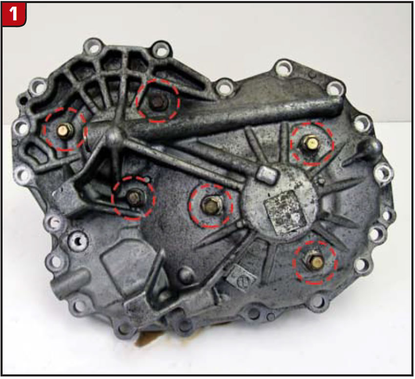
Once the transmission is out of the vehicle, remove the valve body so that the ratio-control motor and arm can be disconnected from the ratio-control motor follower. Next, detach the rear cover and pulley assembly from the case. Once the rear cover is removed, take out the bearing retaining bolts (Figure 1) so the pulley assemblies and belt can be removed from the cover.

Wrap two nylon zip-ties around the belt (Figure 2) BEFORE removal to prevent it from falling apart (not a good situation!).

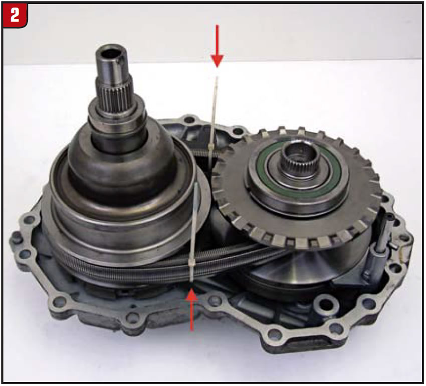
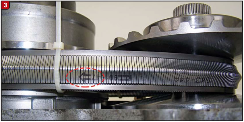
Figure 3 shows a close-up of something to be aware of: the arrow on the belt shows the correct direction of rotation. You’ll need this for reference when the belt is reinstalled into the pulley assemblies, because putting the belt on backwards will damage it and the assemblies.

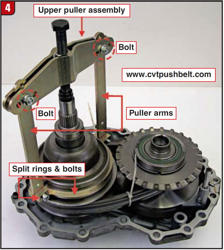
The next step is to open up the secondary pulley so it can be removed, but first you need to have the right tools on-hand. The secondary pulley has a large spring inside that must be compressed before the pulley can be opened. The tool kit for accomplishing this and related parts to complete the process are available in the aftermarket and well worth it. They work as follows:

A split-ring is bolted around the bell-shaped area of the secondary pulley and two arms are connected to the split-ring retaining bolts.

The upper puller assembly and threaded bolt are attached to the top of the arms with two bolts and nuts (Figure 4).

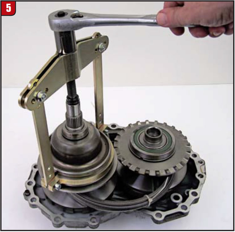
Once the split-ring and upper part of the puller is set in place, tightening the center bolt will relieve spring tension and allow opening of the secondary pulley (Figure 5).

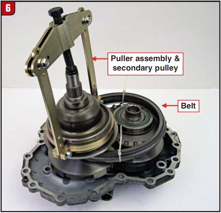
Lift the puller assembly and the secondary pulley out of the cover, then place it inside the primary pulley opening (you may want to put a rag over the primary pulley face to prevent scratching).

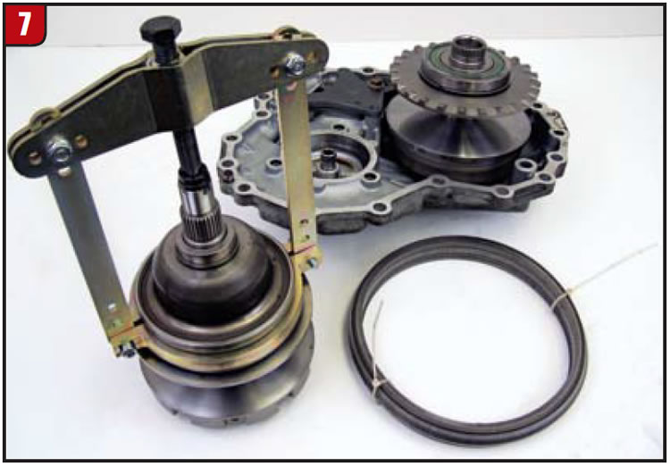
Now, lift the belt over the primary pulley and remove from the cover (Figures 6 and 7).

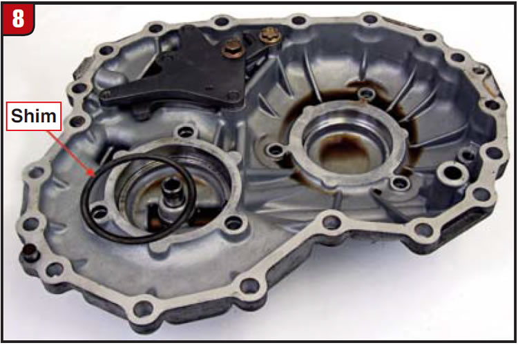
Some units have shims between the rear cover and bearing (Figure 8) which need to be saved for use during reassembly.

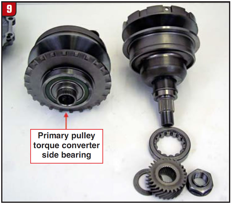
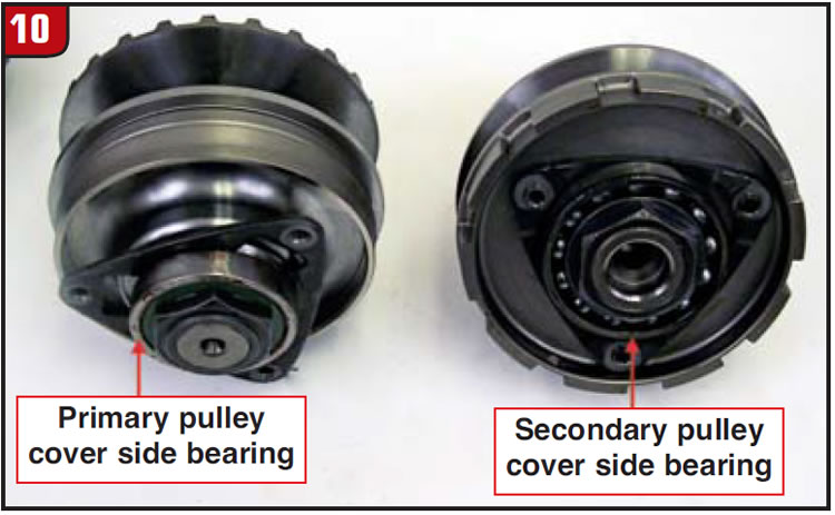
Figures 9 and 10 show the location of the bearings on both the secondary and primary pulley assemblies. There is a primary pulley bearing for the torque converter side and one for the cover side, along with a cover-side secondary pulley bearing. These bearings can be removed with a two-jaw bearing puller or a bearing splitter and puller assembly and pressed back into place with ease. Replacement bearings are readily available in the aftermarket for both JF011E and JF010E units.

Reassembly of the pulleys and belt back into the cover is a snap: simply reverse the process we just went through.

You can see now how easy it is to replace bearings on the JF011E, and once you’re inside the unit you’ll find the rest of the transmission isn’t so scary either. With a little knowledge and the right tools, chasing down noises and repairing CVTs can be very profitable–even if they don’t roll in the door every day.

Jim Dial is a Sonnax Technical Specialist and a member of the Sonnax TASC Force (Technical Automotive Specialties Committee), a group of recognized industry technical specialists, transmission rebuilders and Sonnax Industries Inc. technicians. He will be a seminar speaker on March 13 at the 2015 Auto Tech Expo in Jacksonville, Fla., presenting a further exploration of the Nissan CVT. ©2014 Sonnax Industries

You May Also Like

Sherlock Holmes Approach to an AB60 No-Move Situation

The effectiveness in diagnosing automatic transmission malfunctions is an art form. Although there are similarities among the wide varieties of transmissions on the road, each transmission has its own peculiarities. Aside from having mechanical, hydraulic, and electrical hardware systems to contend with, software/programming issues and various vehicle platforms make diagnostics much more difficult.  Using scopes provides

ab60

The effectiveness in diagnosing automatic transmission malfunctions is an art form. Although there are similarities among the wide varieties of transmissions on the road, each transmission has its own peculiarities. Aside from having mechanical, hydraulic, and electrical hardware systems to contend with, software/programming issues and various vehicle platforms make diagnostics much more difficult. 

GM 6T40 Pump Identification Guide

The 6T40 was introduced in 2008 for General Motors front-wheel-drive cars in the Chevrolet Malibu and has gone through several changes throughout its three generations, specifically in the pump area. The 6T40 is closely related to the more lightweight 6T30 and the heavier duty 6T45 and 6T50. Generation one started phasing out during the 2012

Seeing the Forest AND the Trees

They say that the proverbial phrase “I couldn’t see the forest for the trees” means that a person or organization cannot see the big picture because it focuses too much on the details. Related Articles – 4L60E Harsh 1-2 Shift – TASC Force Tips: Diagnosing 8L45 & 8L90 Shift Complaints – TASC Force Tips: Hydraulics

The Manifold Pipeway

The Honda six-speed transmission has been on the bench of many specialty shops for one reason or another (figure 1). But, for those of you who have yet to lay your hands on one, mounted on the upper side of the unit is one of the largest, if not the largest solenoid and pressure switch

8L90 Vacuum Testing

Below are the diagrams for vacuum testing GM 8L90 transmissions. Note: OE valves are shown in rest position and should be tested in rest position unless otherwise indicated. Test locations are pointed to with an arrow. Springs are not shown for visual clarity. A low vacuum reading indicates wear. For specific vacuum test information, refer

Other Posts

Shift of the shaft: Diagnosing Chrysler 48RE manual shaft issues

The TorqueFlite transmission has been around since mid-to-late 1950s. There have been many changes surrounding the manual shaft and rooster comb through the years. This transmission shaft controls the position of the manual valve that directs oil for the gear ranges, but it also is used for a Reverse light control as well as Park/Neutral

Diagnosing Ford 10R60, 10R80 and 10R140 series speed sensor issues

Ford 10-speed 10R series transmissions utilize four two-wire, Hall-effect sensors — TSS, ISSA, ISSB and OSS — for providing speed signals to PCM or TCM. They are supplied nine volts by a PCM or TCM and assist in the control of clutch apply/release timing that is used in determining shift quality, including TCC. Related Articles

Easy TH400, 4L80-E reverse servo setup: Craft your own tool

While not as sensitive as some shifting bands, the Reverse band adjustment on a TH400 or 4L80-E transmission is critical, and failure to get it right has tripped up even the best builders. There is nothing worse than getting the transmission installed, putting it in Reverse and then not going anywhere or having no engine

Snap-on announces upgrades in diagnostic software release

With its latest diagnostic software release, Snap-on said it has added more location images and larger connector diagrams to its Fast-Track Guided Component Test feature to “give professional automotive technicians increased confidence and certainty in their diagnosis.” Related Articles – Sonnax introduces GM 6L80, 6L90 output planet saver kits – Alto introduces filters for GM

Snap-on-Announces-Upgrades-in-Latest-Diagnostic-Software-Release