Centerline Issues: TCC Frictions Bonded Off Center - Transmission Digest

Centerline Issues: TCC Frictions Bonded Off Center

For several decades the importance of the torque-converter centerline has been hammered home by Don Randolph of DACCO Inc. Don’s sentiments on this subject have been echoed by the torque-converter original-equipment manufacturers (OEMs). In fact, every OEM torque-converter print starts with a true axial centerline, which serves as the reference point for all axial measurements.

Centerline Issues: TCC Frictions Bonded Off Center

Torque Converter Tech Tips

Author: Ed Lee

Torque Converter Tech Tips

  • Author: Ed Lee

For several decades the importance of the torque-converter centerline has been hammered home by Don Randolph of DACCO Inc. Don’s sentiments on this subject have been echoed by the torque-converter original-equipment manufacturers (OEMs). In fact, every OEM torque-converter print starts with a true axial centerline, which serves as the reference point for all axial measurements.

Robert Nankervis, owner of Nan Torque Converters in Belford, N.J., has been aware of the importance of the torque-converter centerline for some time. Robert’s watchful eye for centerline issues drew his attention to some lockup frictions that were slightly off center. Since all their clutch bonding was done in house, he began to examine their bonding process.

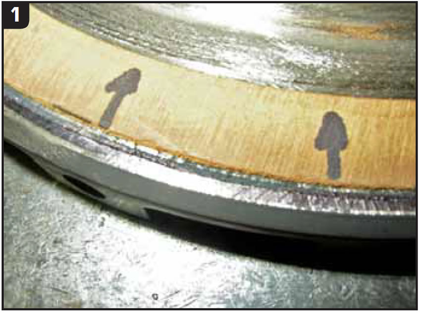
The technician responsible for the bonding process assured Robert that the TCC pistons were properly prepared and the friction material was properly centered on the piston when they entered the bonder. Robert decided to recheck the time, temperature and air-pressure parameters and bond the next run of pistons himself. When he was satisfied that everything was correct, he began the new bonding run. The first couple of clutches that came out of the bonder had the friction material centered properly, but after that the friction material was slightly off center. A closer inspection of the clutch showed a wider glue stain on one side, suggesting that the friction material was being pushed to the side (Figure 1).

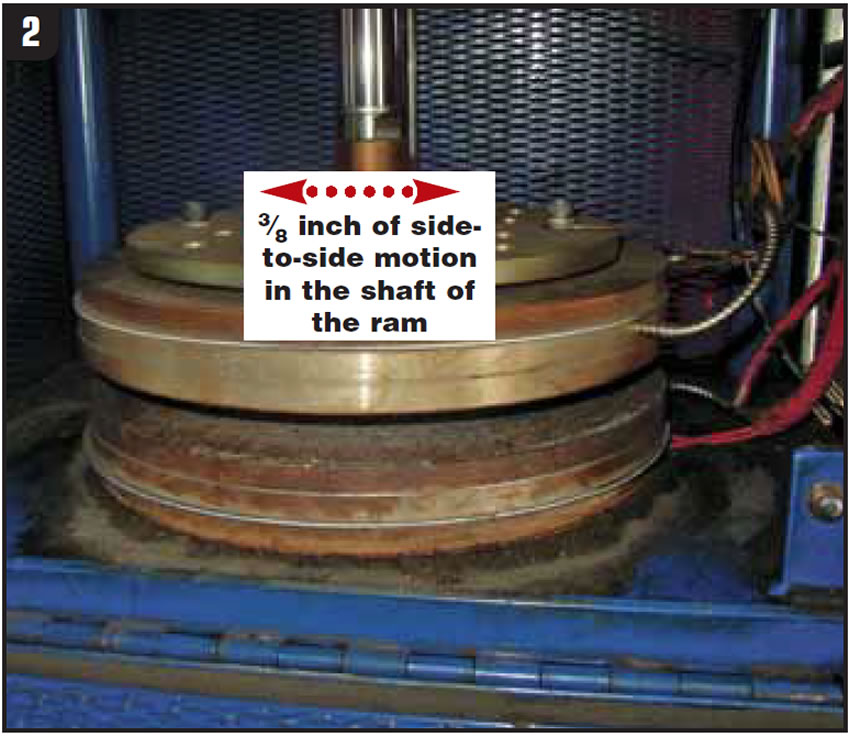
Robert was now convinced that the problem was in the bonder. He allowed the bonder to cool and then started his inspection. The first thing he looked at was the bonder plates. The bonder plates were tightened properly and the mating surfaces were parallel. He next turned his attention to the bonder dies and the piston ram. The dies were removed from the bonder, the ram was stroked to its downward-most position, and the air pressure was released from the cylinder. At this point Robert discovered that there was almost 3/8 inch of side-to-side motion in the shaft of the ram (Figure 2). This movement was caused by a worn lower bushing.

There are two important things to note: 1) while there was air pressure in the cylinder, the piston held the shaft and no side-to-side motion could be felt, and 2) the air pressure remained on the up side of the piston so there was no telltale leak at the worn bushing. As the adhesive turned to a liquid (the flow zone) the friction material would slowly shift from left to right. A new cylinder was bought from a local supplier and the off-center problem went away.

There are a few good reasons to make sure that the friction material is centered properly on your TCC piston. First, the piston and damper assembly can be balanced more easily if the friction material is centered. If the friction material is bonded off center, Robert will mount the piston or damper assembly in the lathe and trim the inside and outside diameters to make them true. Second, the TCC application will function much better if the friction material is centered. The normal operating stresses of the torque converter force the pilot area of the cover forward, making the reaction surface of the cover taper inward. Properly centered friction material will contact the reaction surface of the cover evenly and conform to the mating surface, resulting in a smooth TCC application. When the friction material is off center, the TCC application is quite different. The edge of the friction material that is the farthest from the centerline touches the reaction surface first, and lockup does not apply smoothly.

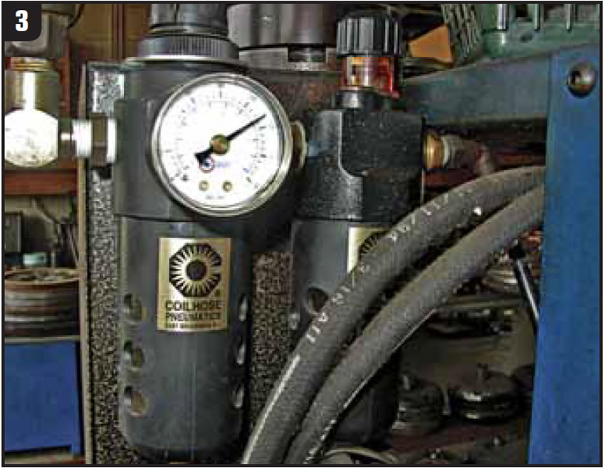
Remember to maintain your bonder properly by making sure that 1) a vapor separator is in the air supply line and 2) an air lubricator with the correct lubricant, maintained to the proper level, is also in the air supply line (Figure 3).

Special thanks to Robert Nankervis from Nan Torque Converters in Belford, N.J., for recognizing this problem, finding the root cause, supplying the technical information and pictures for the article and, most important, sharing his finding with the rest of the industry.

Ed Lee is a Sonnax Technical Specialist who writes on issues of interest to torque-converter rebuilders.

Sonnax supports the Torque Converter Rebuilders Association. Learn more about the group at www.tcraonline.com.

You May Also Like

Sherlock Holmes Approach to an AB60 No-Move Situation

The effectiveness in diagnosing automatic transmission malfunctions is an art form. Although there are similarities among the wide varieties of transmissions on the road, each transmission has its own peculiarities. Aside from having mechanical, hydraulic, and electrical hardware systems to contend with, software/programming issues and various vehicle platforms make diagnostics much more difficult.  Using scopes provides

ab60

The effectiveness in diagnosing automatic transmission malfunctions is an art form. Although there are similarities among the wide varieties of transmissions on the road, each transmission has its own peculiarities. Aside from having mechanical, hydraulic, and electrical hardware systems to contend with, software/programming issues and various vehicle platforms make diagnostics much more difficult. 

GM 6T40 Pump Identification Guide

The 6T40 was introduced in 2008 for General Motors front-wheel-drive cars in the Chevrolet Malibu and has gone through several changes throughout its three generations, specifically in the pump area. The 6T40 is closely related to the more lightweight 6T30 and the heavier duty 6T45 and 6T50. Generation one started phasing out during the 2012

Seeing the Forest AND the Trees

They say that the proverbial phrase “I couldn’t see the forest for the trees” means that a person or organization cannot see the big picture because it focuses too much on the details. Related Articles – 4L60E Harsh 1-2 Shift – TASC Force Tips: Diagnosing 8L45 & 8L90 Shift Complaints – TASC Force Tips: Hydraulics

The Manifold Pipeway

The Honda six-speed transmission has been on the bench of many specialty shops for one reason or another (figure 1). But, for those of you who have yet to lay your hands on one, mounted on the upper side of the unit is one of the largest, if not the largest solenoid and pressure switch

8L90 Vacuum Testing

Below are the diagrams for vacuum testing GM 8L90 transmissions. Note: OE valves are shown in rest position and should be tested in rest position unless otherwise indicated. Test locations are pointed to with an arrow. Springs are not shown for visual clarity. A low vacuum reading indicates wear. For specific vacuum test information, refer

Other Posts

Sonnax unveils valve kits for ten-speed Ford, GM transmissions

Sonnax highlights its valve kits for Ford and GM ten-speed transmissions. Related Articles – Force Control Industries releases transmission fluid for oil shear clutch and brake applications  – TransGo introduces 62TE high pressure kit for vans – OTC releases TJHP15 transmission jack  The first of these is a line of oversized main pressure regulator valve

Sonnax-105740-20K-600
Critical Wear Areas & Vacuum Test Locations for FORD 6R80/6R100

Note: OE valves are shown in rest position and should be tested in rest position unless otherwise indicated. Test locations are noted with an arrow. Springs are not shown for visual clarity. Low vacuum reading indicates wear. For specific vacuum test information, visit www.sonnax.com. Related Articles – Hydraulics Fundamentals: Shift & Relay Valves – Another

Hydraulics Fundamentals: Shift & Relay Valves

Shift valves and relay valves share a lot of the same duties. This article is one of a series by Sonnax exploring how valves and hydraulic circuits work and what results when they quit functioning correctly.

Another 62TE ‘No-Move’ Possibility

Most seasoned techs have several quick diagnostic steps they take when faced with a transmission malfunction. The type of problem and transmission determines which steps to take. For example, a “no-move” condition. Related Articles – Ford 8F35 maintenance tips: Planetary failure and no-pressure conditions – Don’t fear customer complaints about CVTs – Shift Pointers: A Chrysler