R&R Tech
- Author: Jody Carnahan, Warranty Technical Adviser
- Subject Matter: U-series Codes
- Unit: 6R60
- Issue: Reprogrammed TCM Error U0101/U1900
By now, most of us have had to deal with a CAN (Controller Area Network) communication “U” series code at one time or another. Most of the time, diagnosing one these codes is fairly straightforward, given all of the articles and technical publications that have been written regarding these problematic codes. In most cases, it just comes down to identifying the module that isn’t communicating with the other modules on the CAN bus line for whatever reason.
Generally, it’s some type of lost voltage or a poor ground in the circuit wiring to the module in question. So, what happens when all your diagnostic tests and checks take you down a dead-end road, and the actual problem ends up being a component that shouldn’t have had anything to do with a communication error code? I’m sure there may be a few engine drivability techs out there who have run into the situation that I’m about to cover, but it was a first for me.
Our journey began with a 2007 Mercury Mountaineer 4.6L with a 6R60 transmission. This vehicle had just had a remanufactured transmission installed at the shop of one of our wholesale customers. This unit requires the TCM (Transmission Control Module) to be programmed, as it was new and not programmed to the vehicle. For those of you that don’t know, on this unit, the TCM is inside the transmission, integrated with the valve body (mechatronic assembly). As with most installations of this type of unit, the programming is fairly straightforward and we usually have no hitches or problems with the programming procedure. Unfortunately, this case turned out to be the exception.
Shortly after the installation, the shop discovered that the PCM (Powertrain Control Module) had stored a U0101 communication code, which simply means that the PCM did not receive acknowledgement from the TCM within a defined amount of time. This really is not all that uncommon to see, but there also was a U1900 code stored in the ABS module, which prevented the shop from doing any type of reprogramming. In other, similar cases, the cause usually comes down to a ground issue, or just a defective TCM. Since we had another TCM readily available, we decided to just swap it out and try again. As you could guess, this did not help.
We then had the shop start a diagnostic process by checking the resistance of the high-speed CAN wires between the TCM and PCM, and also TCM to the DLC (Data Link Connector). According to the tech, all resistance checks were good, indicating that there were no open wires in the circuit. At this point I began to wonder if we had a problem with the PCM, and/or one of the other modules in the vehicle. My other thoughts left me curious as to what the original issue was that required the replacement of the transmission in the first place. I learned that the vehicle was originally towed in with a no movement concern. I asked them if there were any codes stored in the system at that time. The tech advised that codes were pulled, but he did not write them down. From what he recalled, they might have been “U” series codes along with some transmission-related codes.

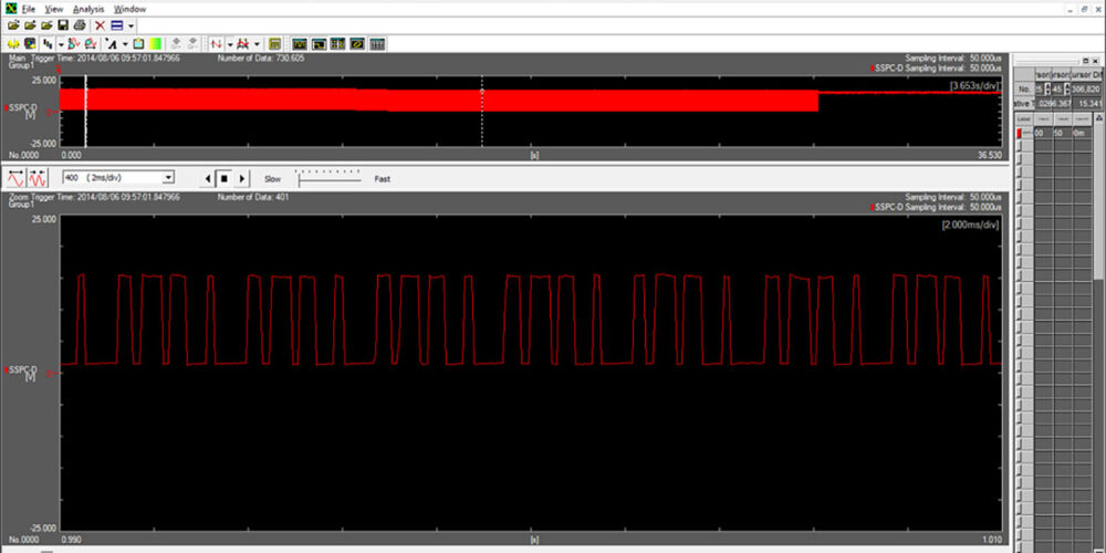
Armed with this new information and assuming that these codes were in the system prior to the transmission failure, it was time to start doing some voltage checks on the high speed CAN wires connecting the modules. I won’t get into the specifics regarding CAN voltages, but I knew I was looking for 2.5V to 3.5V on the CAN high line and 1.5V to 2.5V on CAN low line, and that these voltages need to mirror each other. As luck would have it, the shop I was working with did have a late-model scan tool with scope function. I sent them a copy of the waveform and what it should look like in regards to voltage pattern (Figure 1), and told them that the easiest place to check CAN voltage is right at the DLC.
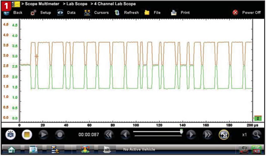
A short while later I got a call back from the tech saying that he must be doing something wrong, because the waveform and voltages they were coming up with were nowhere close to what the sample waveform was showing. In fact, the voltages were spiking off the screen. They took a cellphone photo and sent it to me. The picture did not come out well enough for me to put in this article, but from what I could tell, he was right; the voltages were all over the place. Refer to Figure 1 and visualize it with voltage spikes going off the screen. That’s what theirs looked like.
I did confirm that they were checking the correct pins at the DLC. Typically when we have “U” series communication codes the problem usually is a no-voltage situation, but this case was completely the opposite. Regardless, we had enough evidence that voltage was more likely the cause of the communication issue. We now had to figure out what was causing this type of voltage to be induced into the CAN wiring circuit.
Based on the earlier wiring resistance checks we had performed, I did not think we had a problem with the CAN wiring being shorted to other wires in the harness, but rather induced voltage into the circuit, similar to what you would see when there was a bad alternator causing higher than normal voltages in the TPS (Throttle Position Sensor) and/or speed sensor circuit.
CAN signal wires are a twisted pair of wires much like speed sensor wiring, but unlike speed sensor wiring, the CAN wires are unshielded. Obviously, the first thing I had them check was charging system voltage, which they advised was within spec. I started to sense this was not going to be an easy over-the-phone diagnosis. I asked if there was anything else in particular about the vehicle, such as engine issues, etc. Knowing that we could still communicate with the PCM, I thought that maybe, just maybe, it might give us a clue. We knew it had to be something that was carrying a higher voltage; therefore, what about the ignition system? The tech mentioned that he did not think the engine was idling very well, but not bad enough to give it much thought.
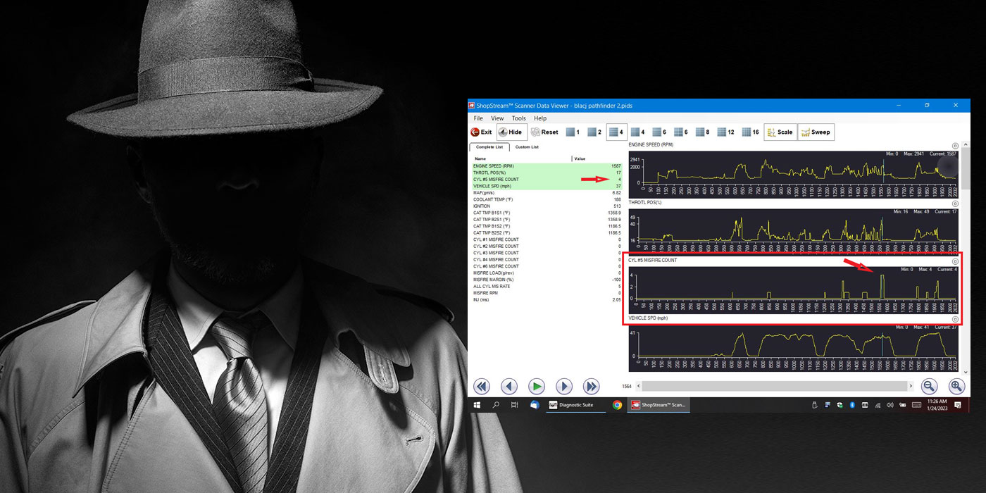
This vehicle uses a COP (Coil On Plug) ignition system, and therefore has no plug wires to interfere with the signal, but we still had individual coils on each cylinder. As I stated earlier, when the vehicle was originally checked out, it had other codes stored but the tech didn’t write them down. With having no misfire codes stored at this time, I had the tech hook scan tool back up and go into mode 6 data, hoping this would shed some light on any misfire activity. Sure enough, cylinder #4 had current misfire activity with no misfire activity on any of the other cylinders. Could it be that a bad coil was causing these voltage spikes?
The COP coils in this Ford application are all identical; the tech removed the #4 coil and swapped it with the number 1 coil. Both coils are on the right-hand bank of the engine, with #1 at the front of the engine, and #4 in the last position on the right bank. The codes were cleared from both modules and the vehicle restarted. The tech left the scanner in scope mode and with the engine running, he noticed right away that the CAN signal looked much like the sample signal that I had sent him. After about a minute of run time, the wrench light came back on. We now had a good CAN signal, but why was the light on?
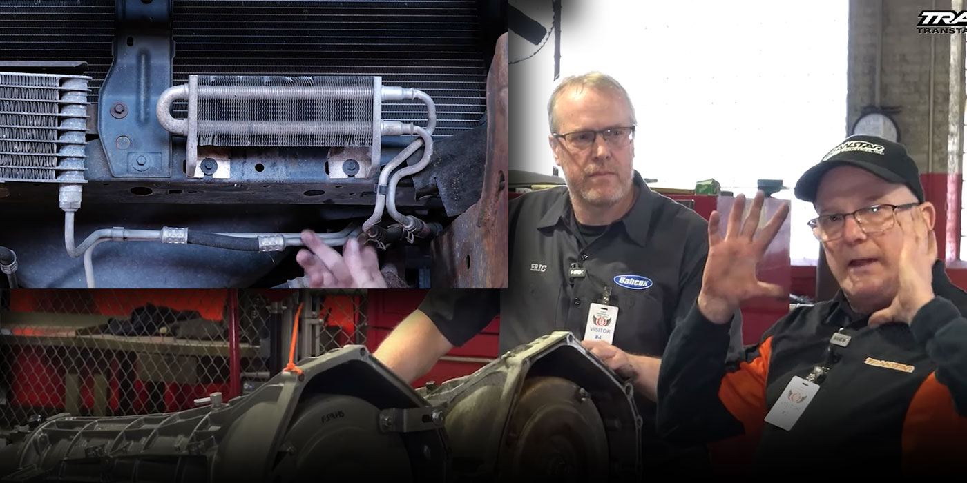
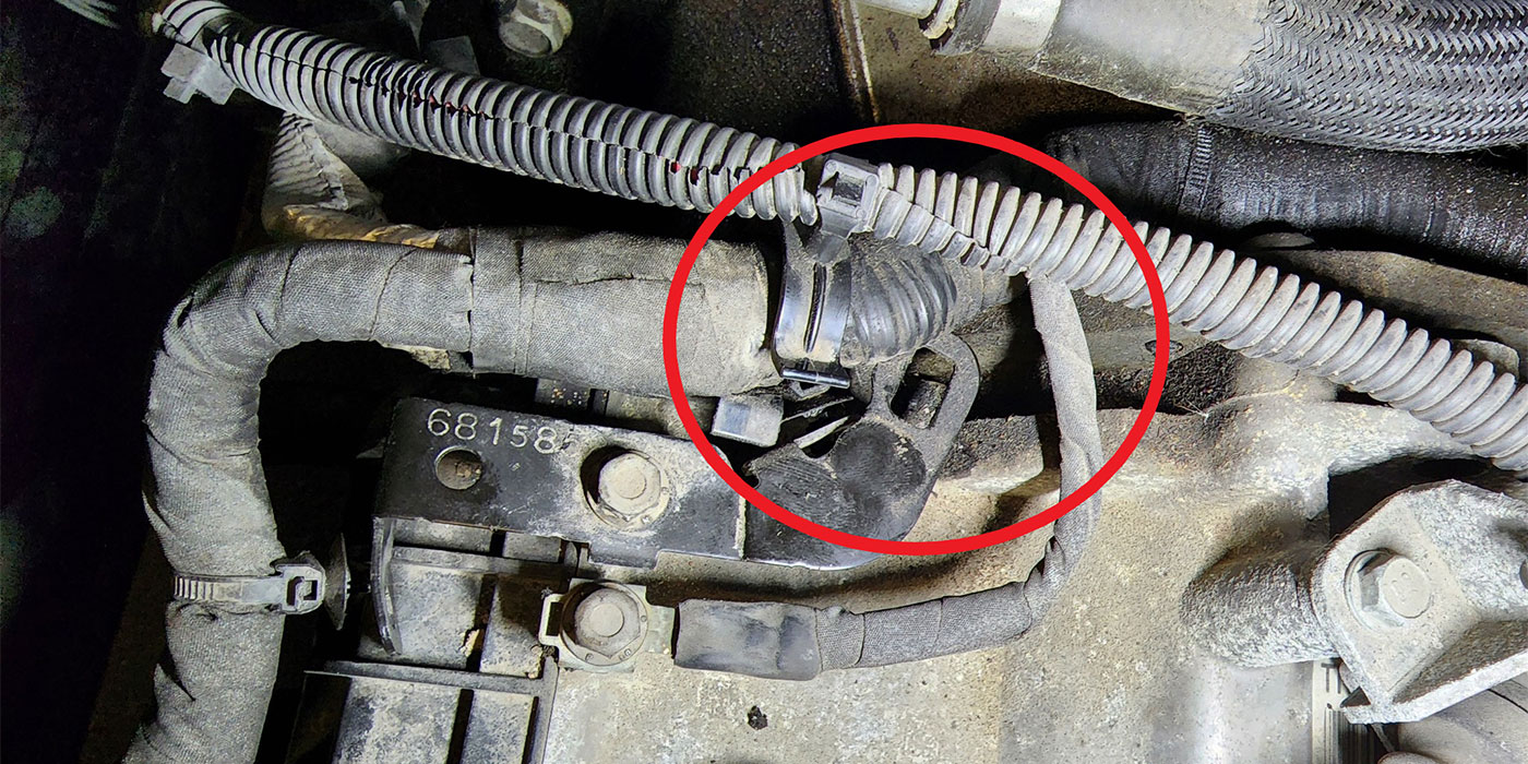
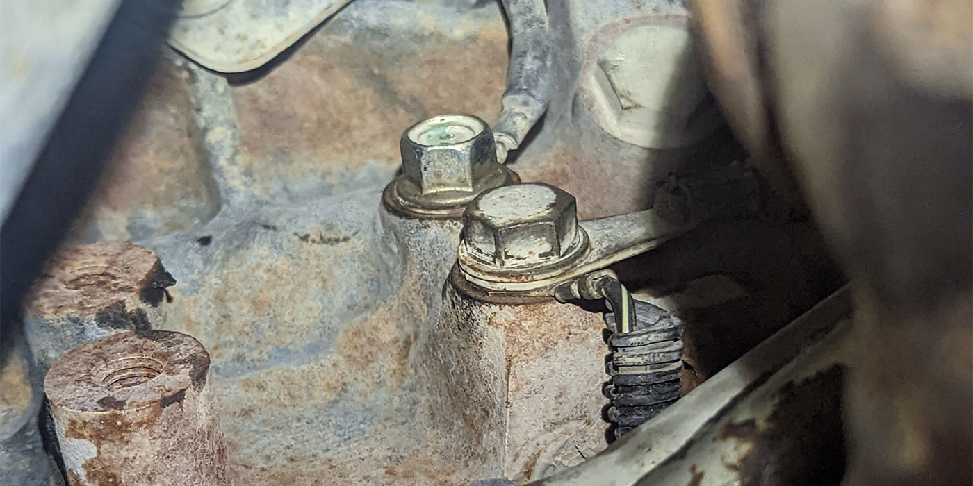
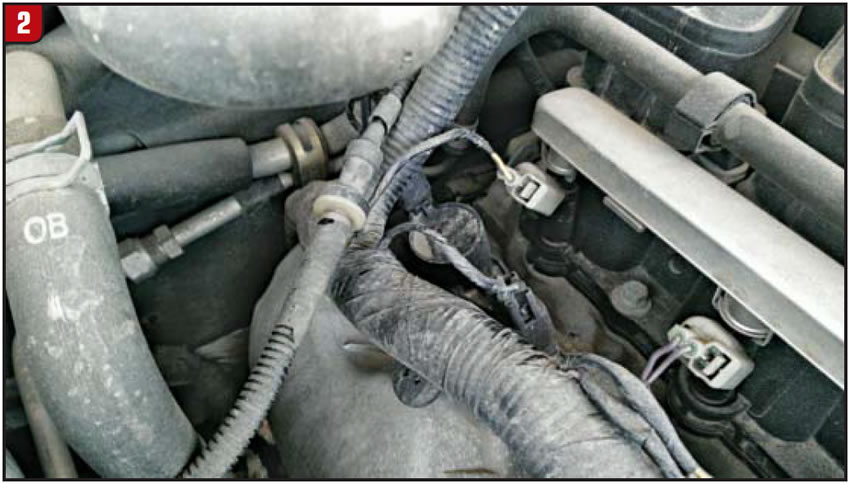
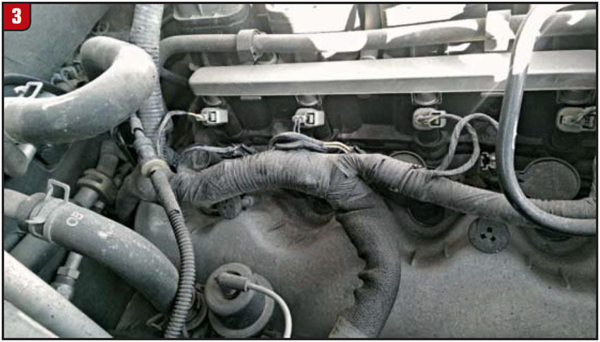
When he again checked the code status, the communication codes were gone but we now had an engine misfire code for #1 cylinder. This concluded that the coil was in fact defective, so the tech replaced it. This corrected all code issues and he was able to complete the TCM programming process. The wiring harness that the CAN wires are housed in run very close to (if not right on top of) coil #4 at the back of the engine (Figures 2 and 3).
Since the writing of this article, our warranty techs have come across this problem on several occasions. In all of these cases the coils were swapped and the communications codes went away. Oddly enough, the codes that were set in each of these situations stayed very consistent, with U0101 and U1900, although the U1900 code was not consistent as to which module it was stored in. Therefore, the next time you encounter CAN communication codes, don’t overlook the NOT so obvious. And don’t be afraid to use mode 6 data during your diagnostic approach. It’s a great tool for situations like this.
Jody Carnahan has been with Certified Transmission since 1986. He began his career directing the formation of our dyno department and has held various technical positions within the company, as well managing a retail location. Today he helps shops diagnose and correct warranty issues. He holds certifications from both ATRA, and ASE.