


Changing a solenoid pack, wiring and computer does not resolve a solenoid electrical code with any Dodge, Chrysler or Jeep vehicle using a 41TE, 42RLE, 45RFE, 545RFE or a 68RFE family of transmissions.

Performing just a resistance check of the solenoids may not always find the problem. The cause can still be with a solenoid pack, wiring or computer, which will require a more thorough diagnostic procedure to help pinpoint the problem area.
One test that has been used to check the integrity of the electrical system is to unplug the TCM/PCM and supply battery voltage to the terminal for the EATX relay’s feed back circuit (or the Automatic Shutdown Relay – ASD). This will allow the ability to conduct an amperage check of each of the solenoid’s entire electrical circuit.
Explanation: When the TCM/PCM activates the relay, it supplies voltage to the solenoids. This same voltage goes to the TCM/PCM for it to know that the relay closed and the proper voltage level is being sup-plied to the solenoids. With the TCM/PCM unplugged and a voltage supply is provided to that terminal, it is also providing the solenoids with that same voltage. This voltage then runs through each of the solenoids and returns to the TCM/PCM at their assigned terminals. The test is to then set your meter up to read amperage. With the negative lead to ground, by probing each terminal with the positive lead you get the amperage of each of the solenoid’s complete electrical circuit.
Not the best approach: The problem with this approach is that if it is not performed correctly, it will damage the circuit. Most of these solenoids measure approximately 1.5 ohms. With each of these solenoids being supplied with approximately 12 volts from the battery, the amperage will be as high as 8 amps. Even though this does confirm a good circuit when under a load, if you stay there too long, it will all go up in smoke.

A safer and more efficient way to check these solenoid circuits is with an amp clamp and a scope. The TCM/PCM monitors the integrity of the solenoid circuit not by amps, but by an inductive pulse when the solenoid turns off. The amp clamp will however give you operational amperage that will typically range from 0.1 amp to 1.0 amps. Watching the amp curve can reveal a bad solenoid coil should it fail. Looking at the inductive spike (or kick) allows you to see what the computer is monitoring.
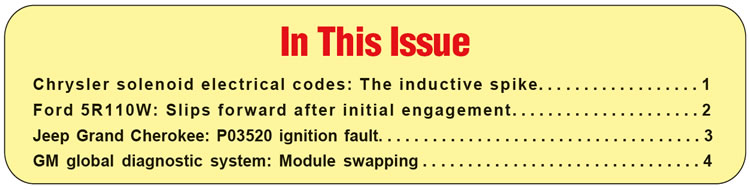
Figure 1 is a screen capture of a scope hooked up to a 2011 Jeep Wrangler with a 42RLE transmission. Notice that when just the ignition is turned on, shortly thereafter the computer turns all the solenoids on and then off to check each circuit for the proper inductive spike.
Figure 2 reveals that each of the four solenoids produced a 42 volt inductive spike when the coil collapsed. If this type of signal is observed yet the TCM/PCM produces a solenoid electrical code, the problem is with the computer as it is not reading the spikes correctly.
If one of the solenoid circuits did not produce this spike and it’s the same solenoid the TCM/PCM sets a code for, then wiring, the solenoid, or terminal contact is still the problem.
Note: Earlier models will produce a 40-volt spike while later models will be around 42 to 46 volts. The change took place around 2000-02 due to changes in computer type.


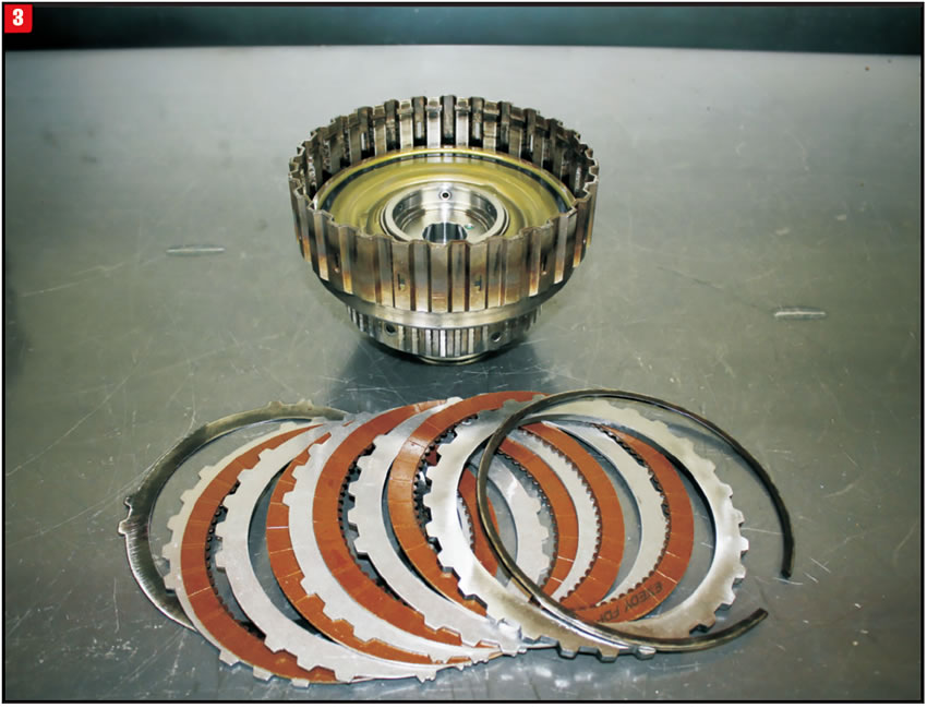
A Ford vehicle equipped with a 5R110W transmission may have a complaint of slipping on takeoff in drive with a throttle opening just above idle. The heavier the throttle is applied, the worse the slipping becomes yet there is no delayed drive engagement. The truck even pulled well enough to allow it to be driven to the shop. Line pressure was checked and found to be within specifications. Upon disassembly of the transmission expecting to find burnt forward frictions, inspection of the friction plates proved just the opposite. They were not bad at all. As a matter of fact, the manufacturers printing can still be seen (Figure 3).
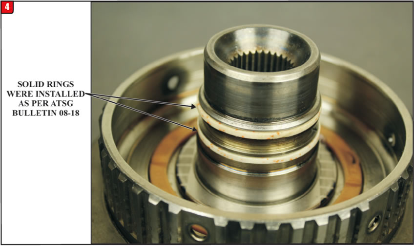
During the rebuild process all parts were examined to the builders’ satisfaction and solid Teflon® rings were installed on the forward drum as per ATSG Bulletin 08-18, shown in Figure 4.
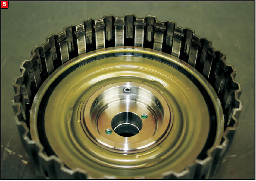
The forward clutch molded piston was also replaced as shown in Figure 5.
Checking the forward clutch with compressed air showed a noticeable improvement than it did with the kit rings. But once the transmission was back in the vehicle the same problem occurred.
The forward drum cracked just below the hub area as seen in Figure 6.
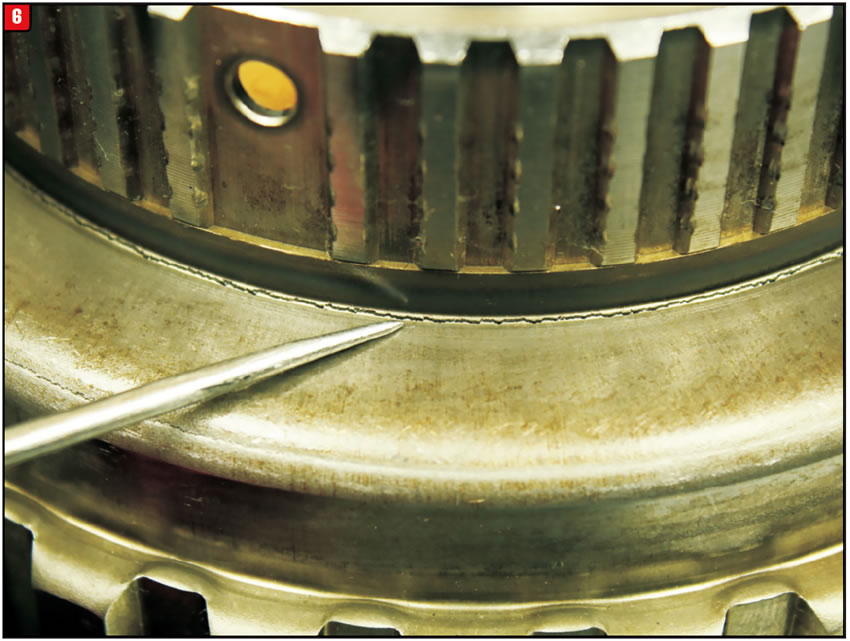
Once the forward drum was replaced the transmission performed flawlessly. This type of failure is considered to be abnormal and can easily be missed especially when the air checks on the center support and through the case were good.


A 2003 Jeep Grand Cherokee 4.0L 4×4 with a 42RE comes into the shop for transmission repair. After installing a rebuilt transmission the vehicle exhibits a misfire. This was not a problem before transmission repairs. Upon inspection, the vehicle has stored a P0352 code for an ignition coil #2 primary circuit fault. Diagnostics related to this code was performed but no circuit problems were found.
Upon further inspection of the PCM, it was discovered that when the control side of the #2 ignition coil was checked at idle, it becomes very erratic. The alternator was unplugged to see if that would make a difference but it did not. It was also noticed that when the engine is revved up to 200 to 300 rpm, the PCM sets codes P0351 and P0353 for circuit #1 and circuit #3 ignition coil primary circuit faults. Before condemning the PCM, all circuits were double checked for shorts, for good power and grounds and all checked good. At this point a new PCM was installed. This too did not fix the problem. Out of frustration the throttle was violently snapped several times when suddenly code P0320 for the crank sensor signal sets.
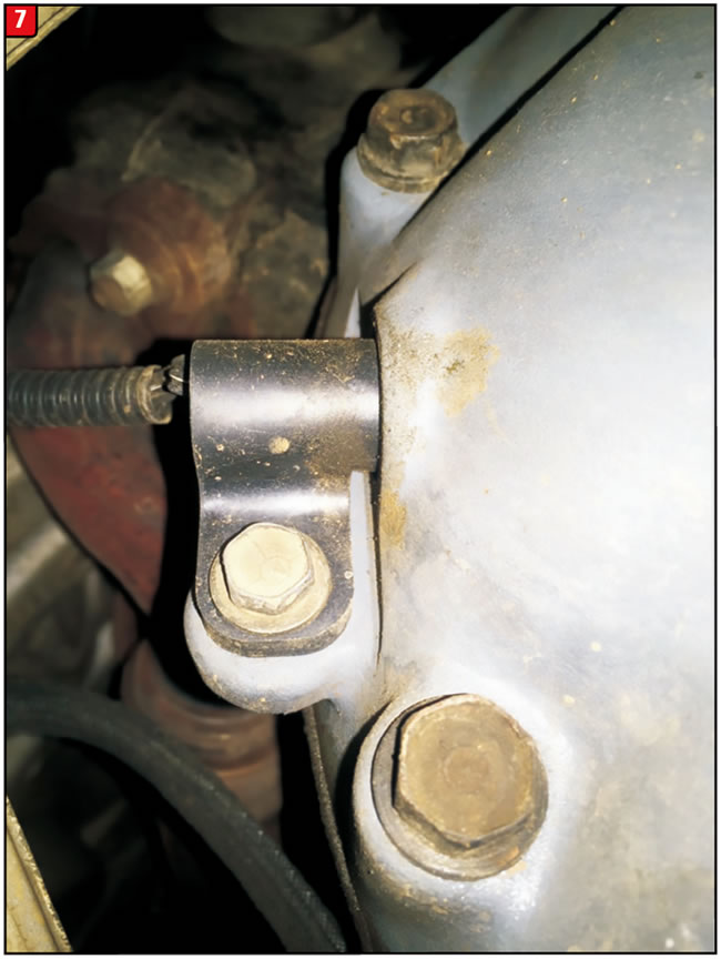
This shop has a couple of men who do the R&R work. One of them will pull the crank sensor off when removing the transmission to prevent the possibility of damaging it when installing the transmission. When he installs the crank sensor, he places a piece of cardboard from a rebuild kit onto the tip of the sensor with which to properly adjust the sensor and there is never a problem. In this situation, the man who never pulls the sensor had to install the transmission with the sensor removed by the other R&R guy. When he installed the sensor, he used the bolt mark left on the bracket as his guide (Figure 7).
This caused the crank sensor to be slightly out of adjustment that prevented it from coding right away. What is puzzling is how it caused P0351, P0352 and P0353 to set. When OE information is looked at for these codes, a misadjusted crank sensor is not one of them. This is the list they provide:
- Good trip equal to zero
- (A142) ASD relay output circuit
- Coil rail resistance
- Ignition coil
- Ignition coil driver circuit open
- Ignition coil driver circuit shorted to ground
- PCM
Once the crank sensor was adjusted correctly, all problems were corrected.
OE install procedure: The crankshaft position (CKP) sensor is mounted to the transmission bell housing and is adjustable via the attaching bolt. A wire shield/router is attached to the sensor. New replacement sensors should be equipped with a paper spacer glued to bottom of sensor. If installing (returning) a used sensor to vehicle, a new paper spacer must be installed to bottom of sensor. This spacer will be ground off the first time the engine is started.
If installing a new sensor, be sure a paper spacer is glued to the bottom of the sensor. If it is missing you will need to obtain a new spacer. The part number is PN05252229. The same applies to reused sensors. Simply clean the bottom of it and peal and stick the new spacer to the bottom. The spacer measures 0.551” in diameter and 0.034” in thickness.
- Install sensor into transmission bell-housing hole.
- Position sensor wire shield to sensor.
- Push sensor against flywheel/drive plate.
- With sensor pushed against flywheel/drive plate, tighten mounting bolt to 7 Nm (60 in. lbs.) torque.
- Route sensor wiring harness into wire shield.
- Connect sensor pigtail harness electrical connector to main wiring harness.
Technicians note: Some models have a coil pack running across the rear of the engine with the connector pointing downward. Caution is required as it is very easy to damage this connector while installing the transmission.

After repairs, a technician may have a complaint of the vehicle no longer starting after swapping what appears to be an identical module from a donor source. In addition, a trouble code B3902 “Incorrect Identifier Received” is set in the body control module as well several other modules. A B389A may also be set indicating an incorrect “Environment Identification” signal.
Unfortunately in this example, returning the original module to the vehicle still resulted in the no start condition.
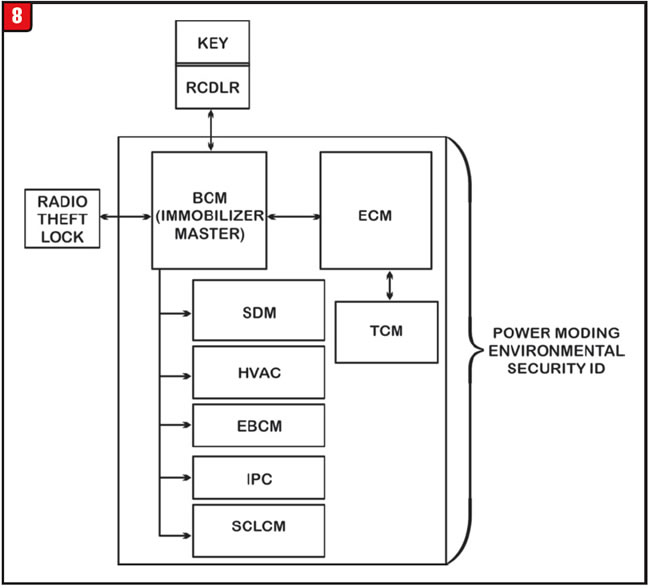
At the start of the 2010 model year General Motors implemented a new type of diagnostic system that includes new security protocols. It is the Global Diagnostic System (GDS) sometimes referred to as “Global A.” There are a number of modules that share the GDS system such as the ECM, TCM, BCM, HVAC, IPC, EBCM, SDM, EPS, HPCM, SCLCM. An example of this global architecture can be seen in Figure 8. The amount of GDS compatible modules may vary depending on how the vehicle is equipped.
The body control module is the controlling module for the GDS system. It sends an “identifier” signal over the serial data lines to which GDS compliant modules must respond by comparing module identification to the identification originally programmed into the BCM.
If the BCM identifier is not recognized or receives an incorrect identifier from one of the other GDS compliant modules, it will respond by preventing the vehicle from starting and the setting of trouble code B3902 and/or B389A.
The reason why the vehicle did not start when the original module was returned to it was because the module “locked on” to the incorrect identification that permanently renders it inoperable.
Do not swap a GDS-compliant module from any source with that of another. In some instances “sleeper” issues may develop which may not materialize until a later date which makes diagnosing the cause all that more difficult.

The following is a list of some of the vehicles that are GDS-compliant:
- 2010-15 Buick LaCrosse
- 2013-15 Buick Encore
- 2011-15 Buick Regal
- 2012-15 Buick Verano
- 2014-15 Cadillac CTS Sedan
- 2010-15 Cadillac SRX
- 2013-15 Cadillac ATS, XTS
- 2014-15 Cadillac ELR
- 2015 Cadillac Escalade, DTS
- 2010-15 Chevrolet Camaro
- 2010-15 Chevrolet Equinox
- 2011-15 Chevrolet Cruze
- 2013-15 Chevrolet Malibu
- 2014-15 Chevrolet Corvette, Impala
- 2014-15 Chevrolet Silverado 1500
- 2015 Chevy Colorado, Suburban, Tahoe 2012-15 Chevrolet Sonic
- 2013-15 Chevrolet Spark
- 2015 Chevrolet Spark BEV
- 2013-15 Chevrolet Trax (Canada Only) 2012-15 Chevrolet Volt
- 2014-15 GMC Sierra 1500
- 2015-GMC Canyon, Yukon
- 2010-15 GMC Terrain

August 2018 Issue
Volume 35, No. 8
- Chrysler solenoid electrical codes: The inductive spike
- Ford 5R110W: Slips forward after initial engagement
- Jeep Grand Cherokee: P03520 ignition fault
- GM global diagnostic system: Module swapping


