


The owner of a construction company called to say that one of his work trucks had recently developed a rather unusual symptom that was a bit upsetting to the driver. The problem was that when the truck was being driven with the tow/haul feature engaged and while coasting to a stop, the transmission would downshift in such a manner that would cause the rear tires to lock up and squeal. The downshift was so abrupt that with the construction trailer hooked up, the truck could be pushed sideways a little. Other than that minor little problem the transmission worked well overall, including good upshifts, reverse and torque converter lockup. There was no check engine light or trouble codes found.
The vehicle was a 2008 Ford F-250 Super Duty equipped with a 5.4L engine and a 5R110W five-speed automatic transmission as well as being 4WD. The truck had also been outfitted with an electronic brake system for the construction trailers that the company had.
When the truck arrived at the shop, a trailer was attached in order to duplicate the customer complaint, and the vehicle was taken for an extensive road test with a scanner hooked up as well as a pressure gauge, just to see what was going on. As expected, initial engagement and upshifts were right on the money whether the tow/haul button was depressed or not, and the shifts were delayed a bit with the button in, which is intended due to computer programming. The truck with trailer was then driven to the top of a fairly steep hill and with the tow/haul button in, started to coast down the other side at about 40 mph. The transmission was in fourth gear and as the brakes were slowly applied, downshifted to third without incident. What happened next was not so subtle. The scanner showed a commanded downshift to second gear, but instead of a smooth transition the engine rpm’s fell back to idle momentarily as if the transmission went into neutral and then spiked back up, locking the rear tires just as the customer stated. Steering control was also affected due to the push of the heavy trailer. The questions became why there was no smooth transition from third to second gear and why did the engine rpms drop to idle. The trailer was also disconnected to see if any change in operation occurred, which it did not. In addition, the truck was driven with the tow/haul button off and during coast down the selector was shifted to manual second, resulting in the same the delayed aggressive down-shift.
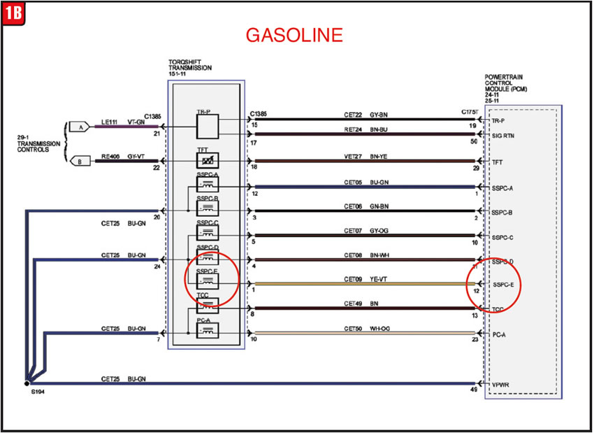
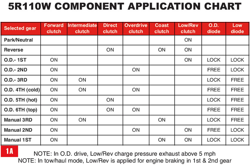
A review of the transmission power flow was needed to determine component application to see what should be firing and when as well as the controls involved. A power flow and solenoid operation chart was accessed and the search began (figures 1A/1B).

The operational differences between a 4R100 and 5R110W are similar to the differences between a 4R55E and 5R55E in regard to how a four-speed transmission becomes a five speed without adding more iron. In effect, the transmission has two main sections comprised of the rear section that provides first, second and third gears like a C6 and the front or overdrive section that provides fourth gear (4R100/5R110W) and in the case of the 5R110W a fifth gear, depending on how many times the unit is cycled. Depending on temperature, a 5R110W can actually obtain a sixth ratio due to how the overdrive section is applied. Cold, the 5R110W overdrive clutch will apply in 2nd, 4th and 6th whereas hot, the OD clutch will only apply for 2nd and 6th gears. Either scenario still results in a five-speed transmission. Speed (gear) numbers are subjective.
Coasting to a stop under normal conditions (tow/haul button off), everything worked well; however, with the button depressed bad things happened. A couple of things occur while downshifting from third gear to second. One function is that the intermediate clutch releases and the other is that the overdrive clutch applies. That operation in itself will not provide engine braking; therefore, something else has to occur to achieve hold back. The additional function needed is apply of the low/reverse clutch. The PCM controls apply and release of both the overdrive clutch via solenoid SSPC-B and the low/reverse clutch via solenoid SSPC-E using a pulse signal.
The vehicle was driven again with the scanner programmed to read both solenoid signals, input/output rpms and the selected gear. The SSPC-B & E solenoids operate the same, although the ramp-up rate is not exactly the same. The SSPC-B solenoid seemed to function normally during upshifts and downshifts, but that was not the case with the E solenoid. There was a noticeable delay of a few seconds during the E solenoid operation before full apply of the low/reverse clutch was achieved, which would explain the rpm drop and subsequent shift shock during the 3-2 down-shift. The low/reverse clutch must be applied to provide engine braking in 2nd and 1st gears, but the clutch is also applied in reverse and reverse worked well. The PCM control signal was normal not only in reverse but also in 1st gear while on takeoff when there is a minimal charge pressure, up to approximately 5 mph, which is then exhausted.
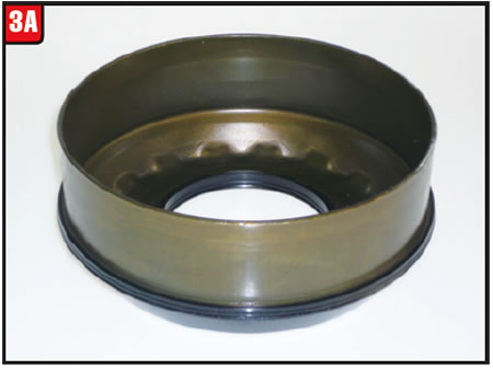
Although everything pointed to a computer signal problem, the transmission pan was dropped for inspection and to check the condition of the fluid. Everything was clean; however, as a precaution the SSPC-E solenoid was replaced and the pan was reinstalled. The vehicle was driven again and of course the downshift issue was still there. Not only were all computer inputs and wiring tested, the computer was reprogrammed in the event something had gone hay-wire, but still no cigar. Due to a lack of options, it was decided to try another computer so a used one was purchased and installed (Figure 2).
After installation the replacement computer was reprogrammed and the vehicle was driven once again, to no avail. At this point, options were limited and even though the issue still seemed to be computer-driven, the pan was removed again along with the valve body so that the low/reverse clutch could be checked.

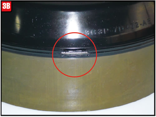
With the valve body removed, the low/reverse clutch clearance was checked and seemed to be within spec. Just for kicks the clutch was air checked to see how it applied and initially application was good, but the air pressure was reduced to about 30 psi and low and behold a leak was detected. It was decided at that point to pull the transmission out and peel it down to physically check the low/reverse clutch and apply piston. Although the frictions and steels were in good shape, such was not the case with the low reverse piston (Figure 3A).
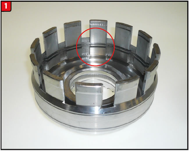
To everyone’s disbelief, a small chunk of the bonded rubber lip was missing which apparently never made it to the pan (Figure 3B). This scenario with any other transmission in the known universe would have been a regular slipping condition whenever the low reverse clutch was applied, including reverse, along with a big bright check engine light and trouble code.
Reverse was not affected, apparently due to the fact that it either is applied or has a charge pressure in park, neutral, reverse and for drive (under 5 mph).
With the coast down into 2nd gear or even a manual downshift into 2nd gear from a higher gear, with the low/reverse clutch completely released, the computer was unable to ratchet up pressure quickly enough to avoid this problem even though it has adaptive learn. Beyond that, not setting a trouble code is even more of a mystery. Although the computer is programmed to control the transmission, sometimes the reverse can be applicable.


Once a transmission has been on the road for a while it is inevitable that certain components will be changed or upgraded and for a variety of reasons. Many part supersessions are done to address failure issues while others are changed to reduce manufacturing cost. Such was not the case involving the input retainer for the 45RFE family of transmissions.
When the A604 was released in the late ’80s, one of the troublesome areas to surface almost immediately had to do with the underdrive backing (OD/UD pressure) plate tapered snap ring. Due to breakage problems the snap ring was redesigned several times until finally in 1997 Chrysler modified the input retainer and OD/UD pressure plate in order to accommodate yet another snap ring design. Once done, snap ring breakage issues became a fraction of what they were previously.
The input clutch assembly used in the 45RFE family of transmissions is a carbon copy of the A604, only a bit larger (Figure 1). One would think that, with the hits Chrysler took on the chin with the A604, the OD/UD pressure plate tapered snap ring used in the 45RFE would be indestructible from the get-go. Although snap ring breakage was not as prevalent early on as with the A604, there were enough to prompt Chrysler to redesign the snap ring in 2003. That change worked fairly well, which should have been the end of the story; however, nothing stays the same forever.
When Chrysler launched the 68RFE in 2007, the focus was not only to have a beefier transmission but also to provide commonality wherever possible. Components such as the pump were redesigned on the 45RFE (5-45RFE) to mimic the 68RFE. An area of noticeable distinction between the 45RFE and 68RFE models was the input clutch assembly. The 45RFE/5-45RFE units use double-sided frictions for overdrive and underdrive clutch packs, whereas the 68RFE uses single-sided plates. As a result of this change the input retainer and pressure plate had to be modified accordingly. To accommodate all models, the snap ring grooves in the input retainer were repositioned and the new retainer will now service all models provided the correct pressure plate is used. This dual purpose pressure/backing plate gets a lot of action and has certainly been changed more than once (Figure 2).
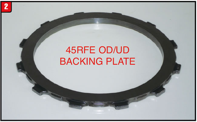
The original 45RFE OD/UD backing plate was actually available in three different thicknesses similar to the A604; however, Chrysler decided that as part of the upgrade in 2007 a selective plate wasn’t necessary. Apparently, a precise clutch clearance is not all that relevant. Identification of the backing plate design is not too bad between year breaks especially when viewed from the side (Figure 3).
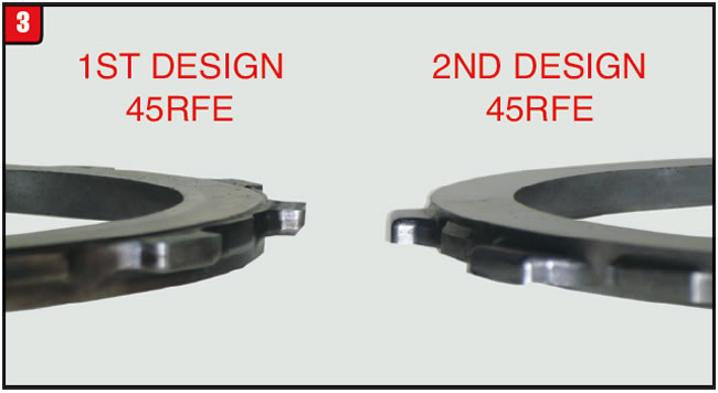
The backing plate for 1999-06 applications have the drive lugs positioned almost completely to one side whereas, the 2007-up plate has the drive lugs positioned more toward the center. In addition, the friction surface on the overdrive clutch pack side of the plate has a reduced outside diameter as was done to the A604. Although there are no selective backing plates, there is one other little wrinkle that has to do with model differences pertaining to overall thickness. The thickness of the 45RFE backing plate is .295 and the 68RFE backing plate thickness is .345. An easy way to distinguish between models is by the number of dots which are indented into the drive lugs. The 45RFE plate has two dots and the 68RFE has one.
If during rebuilding the input retainer has to be replaced, an upgraded service package will have to be purchased due to the individual retainer not being available separately. Although the service package is listed to repair both the 45RFE and 68RFE, that is not exactly the case. The input retainer and tapered snap ring contained in the package do apply to both models; however, the backing plate included is only for the 45RFE. If working on a 68RFE and if the backing plate is also required, then the specific 68RFE plate will need to be purchased separately.
At the time of the release of these new components, there were specific part numbers that referred to either the update package or the individual items, while other items were deleted, such as the first-design input retainer and selective backing plates. Currently, Chrysler only lists a part number for the complete package, second-design tapered snap ring and backing plate for the 68RFE. Part numbers for the first and second design 45RFE backing plates are not quite so visible.
- The part number for the upgrade package that includes the second design input retainer, second design snap ring and second design 45RFE OD/UD backing plate is 68009648AD.
- The part number for the second-design wide-tapered snap ring is 4799111AB.
- The part number for the first-design 45RFE backing plate is 68009108AA and the second-design part number is 68009902AA.
- Lastly, the part number for the 68RFE backing plate is 52119658AD.
Hopefully these numbers will stay put for a while.


Much that has been written about changes to the 6T40 is in regard to GEN 2 design upgrades. GM started to phase in GEN 2 changes beginning in 2012 but was extended well into 2013 and even 2014. Actually, changes can occur even though the transmission has been on the road for a short time as is the case with the 6T40. Certain changes made early on continued into later models right up to today while other upgrades have limited year breaks.
One of the main failure areas that have plagued both GM and Ford has to do with the rotating clutch assembly, and a lot of changes have occurred especially on the GM side of the fence, mainly relating to GEN 2 applications. One change that did occur to GEN 1 applications had to do with the 3-5/reverse backing plate snap ring having a tendency to pop out. That issue was addressed with a drum/backing plate upgrade which is included in a service package along with an improved snap ring
under part #24255922.
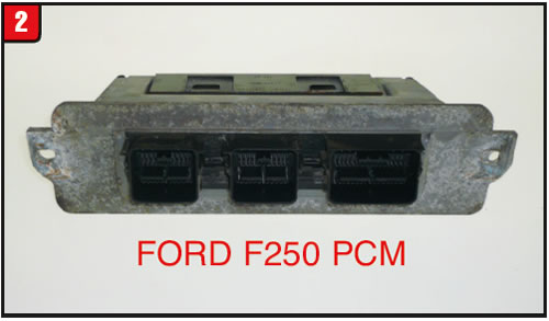
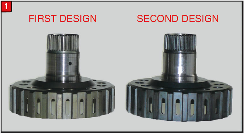
Another modification has been released that also pertains to the rotating clutch, specifically the 4-5-6 bonded retainer and clutch hub. Apparently GM had an issue with the overall length of the clutch hub and needed to make a change to not only the hub but the bonded retainer as well. The length of the hub was increased approximately 0.080 at the clutch spline area (Figure 1). The first design hub length is 0.900 and the second design hub length is 0.980. Other than the length both hubs are the same.
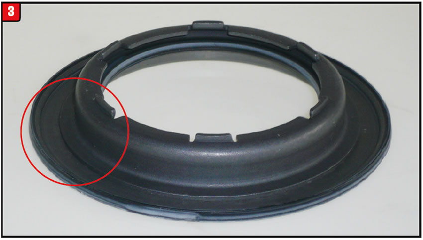
To accommodate the additional length of the clutch hub, a modification had to be made to the 4-5-6 bonded piston retainer. The first design bonded retainer had a 90° lip around the upper section of the retainer (Figure 2). If the first design retainer and the second design clutch hub are used together, interference will exist between the two.
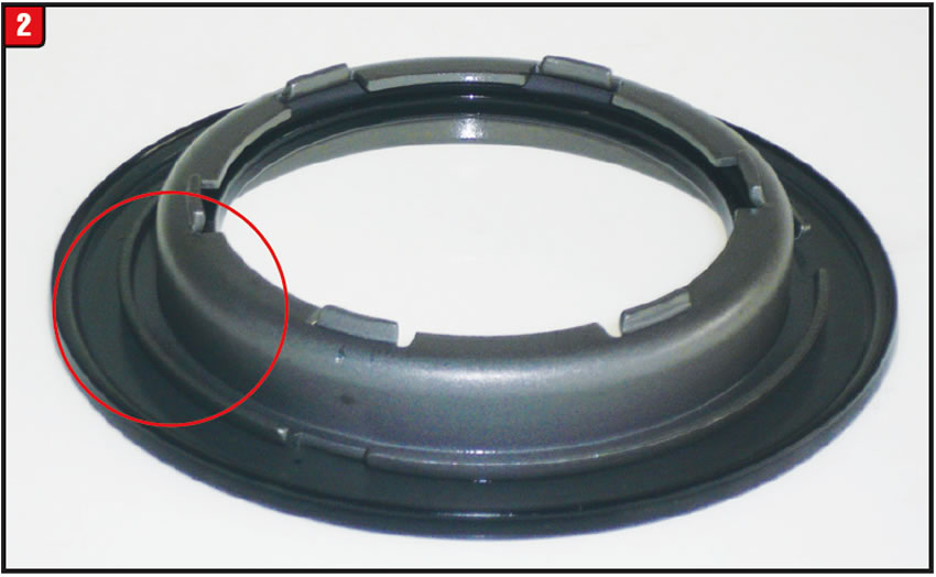
To avoid the problem GM redesigned the retainer and omitted the 90°bend altogether resulting in a flat surface (Figure 3). Both components along with a new snap ring are included in update package part number 24270796. The new design hub can be purchased separately under part number 24247699 for models 2010-up.
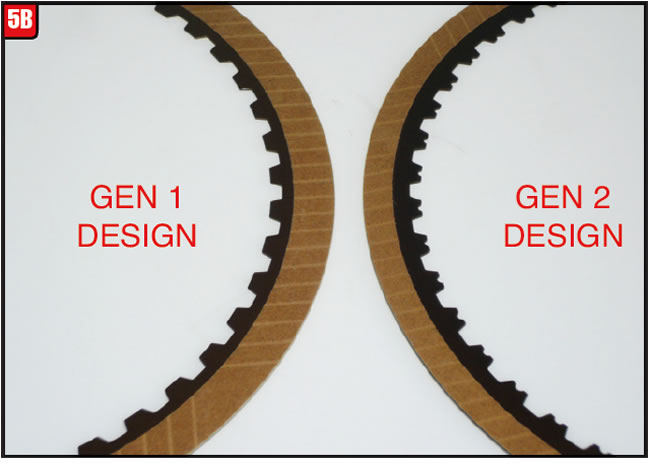
Just like the 6T70, big brother to the 6T40, GM decided to modify all the friction plates used in the transmission with the launch of the GEN 2 upgrades. Not only did these changes affect the friction material, but the waviness of the steel core was modified as well. In the rotating clutch assembly, the 4-5-6 friction was changed from a tan material, similar to Ford, to the normal gray GM material (Figure 4A).
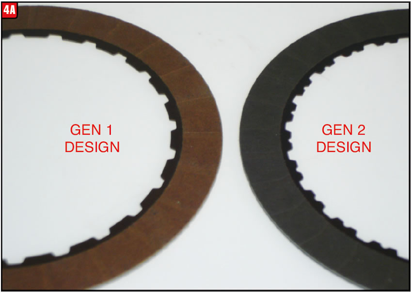
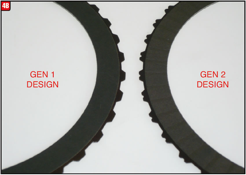
As with all new GEN 2 friction plates, an easy way to distinguish them from GEN 1 is by a notch in the teeth. The 3-5/reverse friction material is gray on both versions; however, the GEN 1 friction plate was smooth, whereas the GEN 2 plate is grooved (Figure 4B). In addition, waviness was increased on the GEN 2 plate.
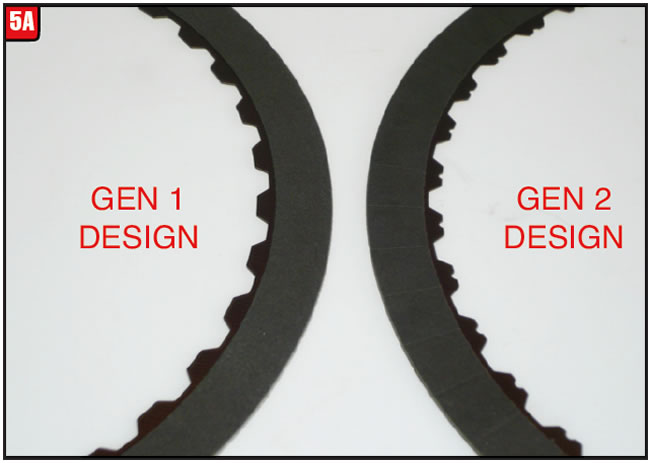
The three stationary brakes also got facelifts in order to improve shift quality and minimize drag while in the release position. On GEN 1 applications the 1-2-3-4 and 2-6 friction plates were the same part number however, that changed with GEN 2. The first design frictions had smooth lining on both clutch positions and the lining on the new design 1-2-3-4 is also smooth. The difference is in the waviness between the two 1-2-3-4 plates with the GEN 2 plate having more of a wave. The 2-6 friction plate wave design is the same between GEN 1 and GEN 2; however oil grooves were added to the GEN 2 friction material (Figure 5A). Maybe at some level this all makes sense.
To reduce drag with the clutch released, the inside diameter of the low-reverse friction material was increased (Figure 5B). The GEN 1 friction has six waves, whereas the GEN 2 friction has nine, although they are both the same height. In addition, there is a GEN 3 version that is a segmented friction design like other newer friction plates.
The beating heart of the 6T40, the pump, has been tweaked a bit although the changes have not been too brutal to date. Unlike the 6T70, which has a chain driven remote access pump, the 6T40 pump is direct drive (Figure 6). The pump cover (stator support) is almost identical between GEN 1 and GEN 2 models. One exception has to do with BAS (belt alternator starter) applications due to a difference in oil passages.
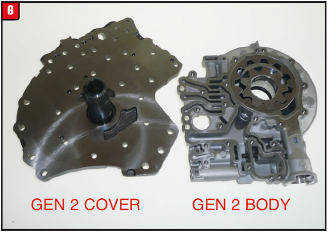
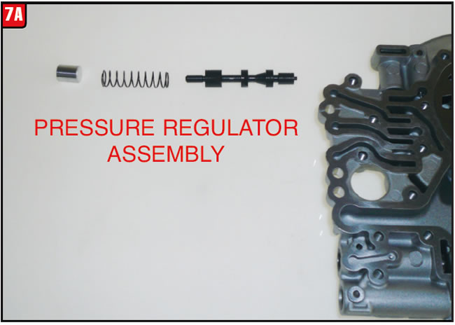
Externally, GEN 1 and GEN 2 pump bodies also look the same, with minor differences. The change from GEN 1 to GEN 2 models has to do with the pressure regulator valve (Figure 7A).
To accommodate pressure variations between models the pressure regulator spring tension was changed and is now color-coded green (Figure 7B).
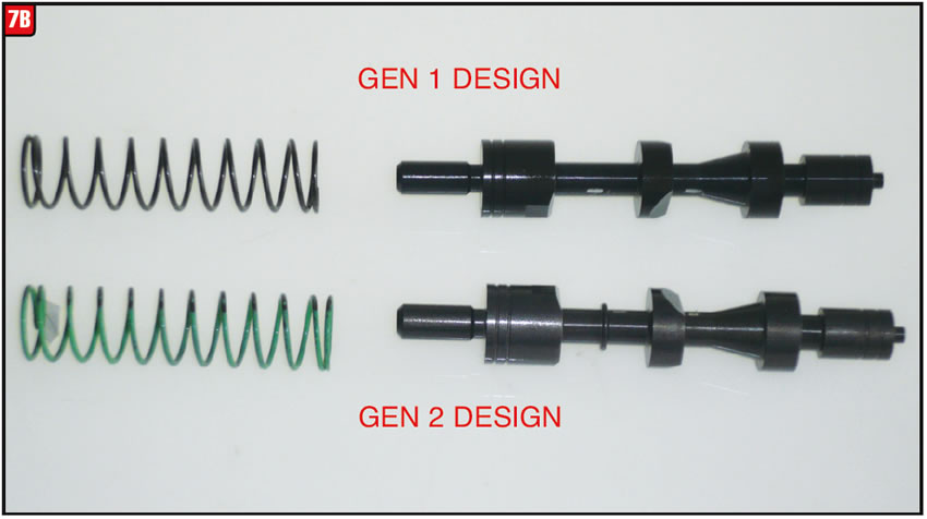
In addition, the land at the end of the valve, which is for control oil, was reduced on GEN 2 pumps, which means the valve bore of the pump body is also different. The new valve can be identified by an identification ring. The land diameter on the GEN 1 valve is .355 and the GEN 2 diameter is .340. The part number for the GEN 1 pump is 24256951 and the part number for the GEN 2 pump is 24253822.
It remains to be seen what will happen next.

August 2016 Issue
Volume 33, No. 8
- Ford Pickup Downshift Apply Issue
- 45RFE/68RFE Input Retainer Update
- GM 6T40 Ongoing Model Changes


