


A 2006 Jeep 4WD had to be towed to the shop because of a no-movement condition. The vehicle had a 3.7L engine and a Mercedes 722.6 transmission. The unit was disassembled and a broken output shaft was found to be the problem. Beyond that, the transmission was in fairly good shape considering the 96,000 miles on it and the occasional mud-dubbing weekends.
The transmission was rebuilt using the customary replacement parts and procedures. As a precaution the torque converter was also gone through and, as with the trans, was not in too bad a shape. The unit was reinstalled, filled with the proper fluid and taken for a road test. Although the vehicle went down the road, which was good, the shifting (up and down) was a bit harsh, which was bad.
Transmissions today much of the time require a relearn process to be performed after a major repair is done. Usually this can be done with a standard hand-held scan tool or even by disconnecting the battery to dumb down the computer back to the launch point. Unfortunately, this was not the case with the Jeep. Remedying the problem required resetting the shift adapts back to zero, which was not doable with the existing shop scan tool.
There are certain functions, such as resetting the shift adapts on the Jeep in question, that require a scan tool or laptop computer that can accommodate OEM program capabilities, like Chryslerʼs wiTECH. A technical service with the Chrysler subscription for wiTECH was contacted and a technician was able to reset the shift adapts so that the transmission would work as intended. Everything worked well and the vehicle was delivered, only to return a month later with – guess what – harsh shifts!

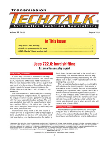
After road-testing of the vehicle and checking of computer data to determine why the shifting issue returned, the customer finally recalled that the condition showed up shortly after an engine-stall problem occurred. The cause of the engine-stall problem had to do with the ignition switch. The Jeep ignition-switch problem had nothing to do with the GM debacle (no sympathy pains), but rather the ignition-switch module (Figure 1). Apparently, one good road bump was enough to take it out.

At the time the ignition-switch module was replaced, the engine started fine, but the shift adapts went back into the dumpster. After trying another one of the shopʼs handheld scan tools, which also didnʼt work, the technical service with the wiTECH link was contacted to do the thing. Just like the first time, the shift adapts were reset and the transmission went back to normal.
In the end, rather than doing a transmission repair or dealing with some other vehicle glitch, systems are interconnected and may require external tweaks beyond the capabilities of what a shop has in its arsenal.


A customer showed up with a 2006 Chevy Suburban that was making a knocking noise that would increase with engine speed. The vehicle had 102,000 miles on it and was equipped with a 5.3L engine and a 4L60-E transmission. Knocking noise aside, the unit seemed to work fairly well but did have some debris in the pan.
The noise was coming from the front end of the transmission; therefore, it was removed and disassembled to determine the problem. The source of the noise became obvious once the pump was split apart: a cracked vane ring. The pump required replacement because of vane-ring wear. The rest of the transmission was in good shape, other than the basic soft parts that were replaced.
The unit was rebuilt and reinstalled. The good news was that the noise was gone; the bad news was that the vehicle didnʼt seem to function normally. Adding the fluid took more time than it should have and the vehicle seemed sluggish on takeoff, almost as though the torque converter was not completely filled, and for good reason – it wasnʼt. After checking line pressure and giving the valve body the once-over, the builder determined that the unit had to come out.
Based upon the symptoms and the only hard part that was replaced, the pump was inspected first. As it turns out, the replacement pump was the wrong one. To be more exact, it was the pump cover that was wrong.
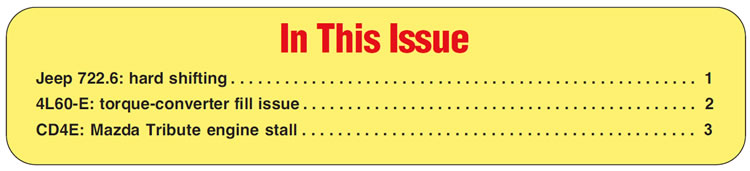
Since the 4L60-E, let alone the 700-R4, has been in existence for more than 20 years, several modifications have been made to internal components, especially the pump. Changes to the pump that started in late 2005 were more extensive and took longer to implement than previous updates. What began in 2005 took about a year and a half to phase in across the board, all of that to add an input-speed sensor (Figure 2).
Several components were involved in the modification, and each step had its own time frame based upon application. The addition of the ISS (TSS) helps to provide better control of functions such as lockup. By 2007, everything had been switched over to the new version, designated 4L70-E. Although specific time frames are important, physical identification is paramount to avoid rebuilding issues.
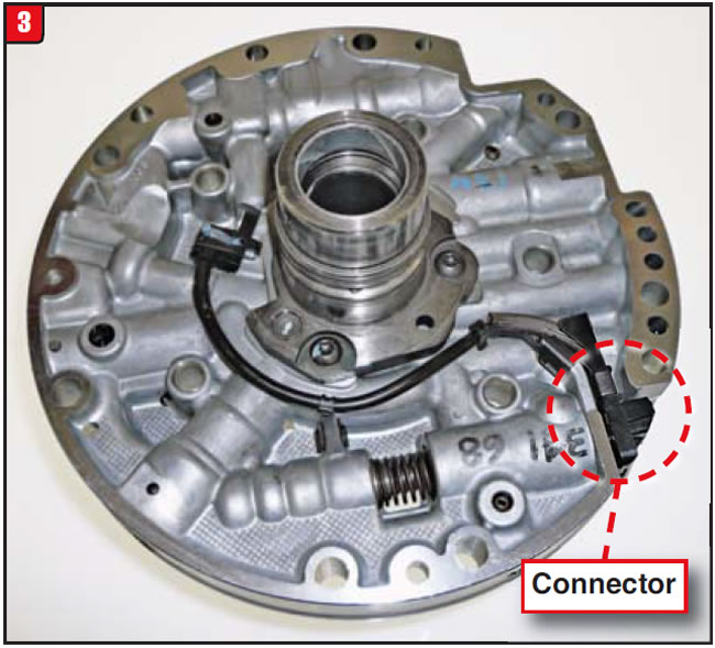
The pump cover was the main component changed to accommodate the ISS. The finished product was modified so that the ISS would “push through” the cover and stator support to pick up a signal from the input shaft. It was also cut to enable the ISS harness to connect to the main harness (Figure 3). The casting changed a couple of times before the boss, where the ISS hole is situated, would accommodate the sensor and hold-down bolt. The web cutout for the sensor connector also has to be there.
The key is knowing the position of the oil holes in the stator support in relation to the input-shaft sealing rings.
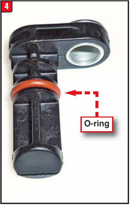
Certain models may be the ISS design, as far as the hard stuff is concerned, but not use the sensor. In that case, a plastic plug, with O-ring, must be used (Figure 4).
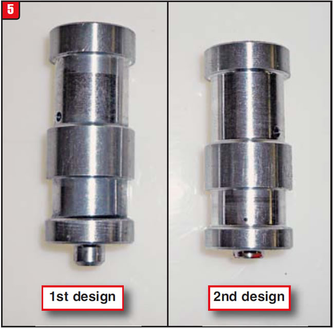
Another item change relating to the pump cover is the boost-valve sleeve. Because of the harness-connector cutout at the outside diameter of the cover, the boost valve and sleeve had to be shortened by about 0.100 inch (Figure 5). The early-design length is about 1.910 inches and the late design is 1.810 inches. Even the TCC apply valve changed from a two-spring design with a pilot to a one-spring design with a hole.
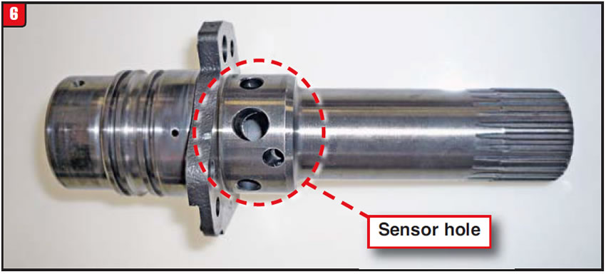
The oil holes in the cover must correspond to the oil holes in the stator shaft. The holes were repositioned to make room for the sensor hole, which is the largest hole in the shaft (Figure 6). If the large hole is there, itʼs the second design; if not, itʼs the first design. There are still two different lengths of stators, the short one for 245mm and 298mm converters and the long one for 300mm converters.
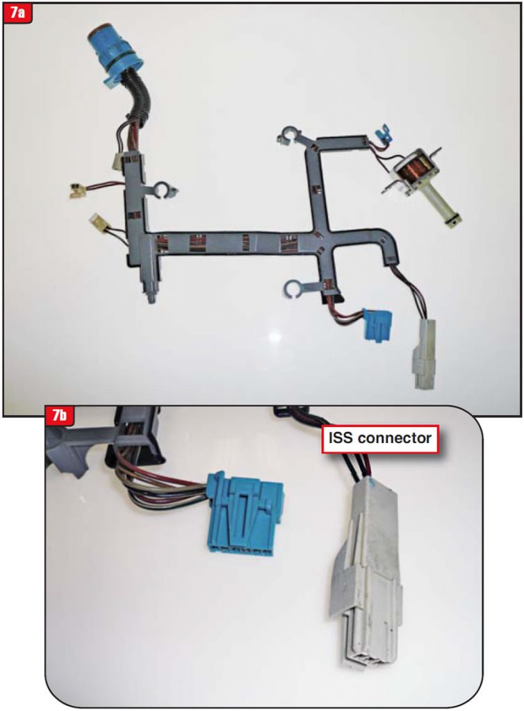
GM has used a slew of electrical harnesses in 4L60-Eʼs since 1993, and the changeover to the 4L70-E required more yet. The new harness has an additional connector for the ISS (Figure 7). As if that were not enough, the electrical harness was changed again in 2009 due to the IMS (internal mode switch) upgrade. There is no end in sight when it comes to electrical changes.
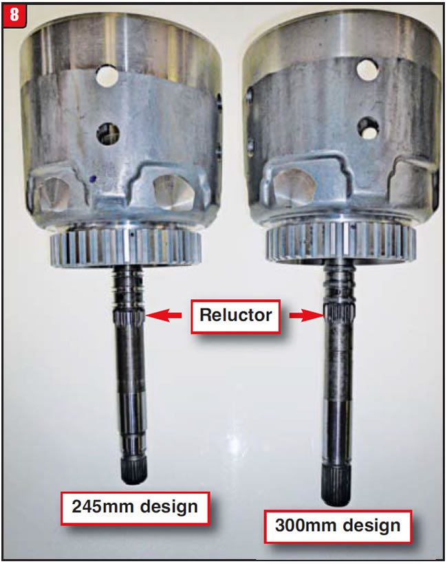
The other component that goes hand in hand with the pump is the input shaft, which presses into the input housing. Itʼs the shaft to focus on. To signal the ISS, a reluctor had to be added to the shaft. This was done by adding a boss to the shaft and then cutting teeth into it. The position of the boss required moving the sealing rings rearward by more than 0.100 inch. Itʼs easy to spot a 4L70-E shaft (Figure 8). One little wrinkle is application. For years there have been three different shafts, based on torque-converter diameter: the 245mm, 298mm and 300mm. Figure 8 shows the 245 and 300mm types, with a reluctor.
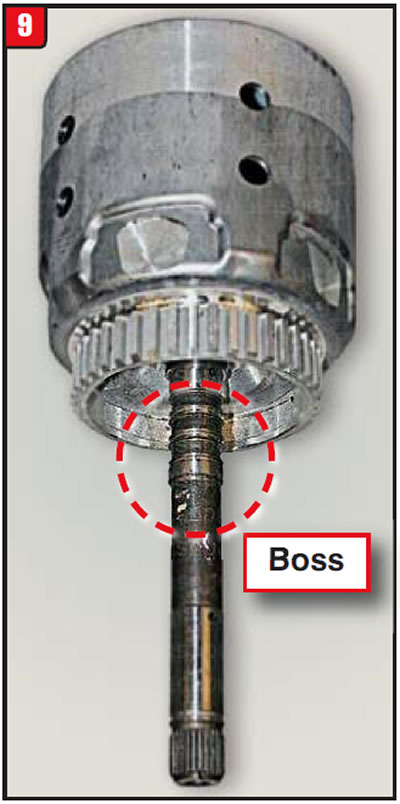
The 298mm, once the backbone of 4L60/4L60-E models, ended up getting whacked (phased out), but not before being modified. The boss was added to the shaft; however, the splines were never cut in (Figure 9). This is where the problem arose during assembly.
When the builder exchanged the pump, he assumed that the ISS was not needed because there was no cut reluctor on the shaft. The pump he chose did not have the ISS but did have the hole in the cover for the sensor. Rule number one: Fill the hole with something, either the sensor or the dummy plug. If the hole is left open, converter pressure will dump and big problems will arise, such as not filling the converter properly.
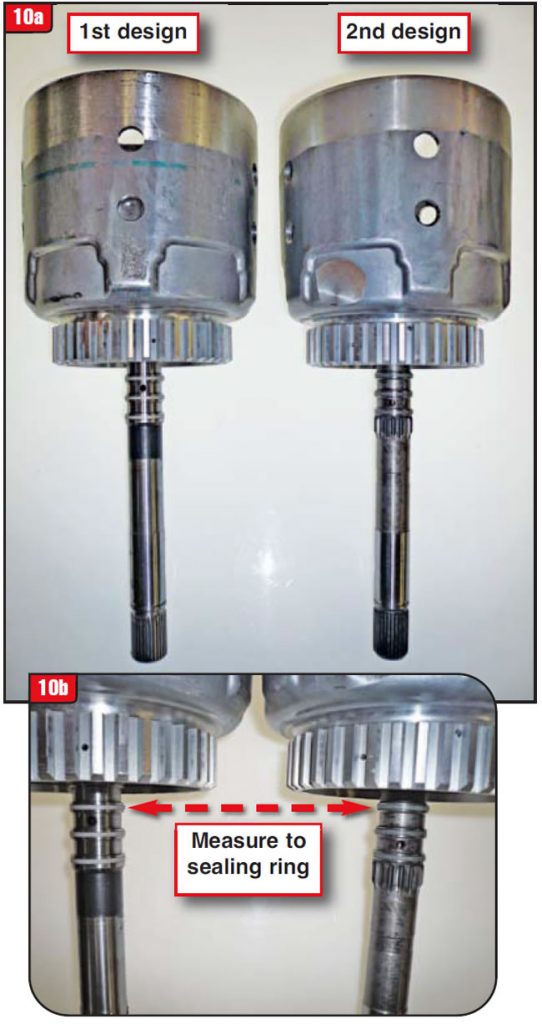
In addition to problems with leaving the sensor hole open is the mismatch of the first- and second-design pump covers and input shafts. Not having the correct matchup will result in clutch-apply issues. Regardless of whether the input-shaft boss is cut, it is the spacing of the sealing rings that counts (Figure 10). Measure from the end of the clutch splines of the housing to the top sealing ring in order to determine the design. To avoid problems, know the parts before installing them.


The owner of a 2005 Mazda Tribute was complaining that at times the engine would die when the vehicle was coming to a stop. In addition, just shifting the transmission into drive or reverse would cause the engine to stall, unless the engine was off idle. The transmission upshifts were good and the torque converter did lock up correctly and would release when the driver tapped the brake pedal.
The vehicle was equipped with a 3.0L engine and CD4E transmission and had 160,000 miles on it. The engine also ran well. A scan tool was connected to the vehicle and revealed that in gear, at idle, the difference between desired TCC slip and actual TCC slip was substantial. Based upon the findings, the unit was removed and disassembled.
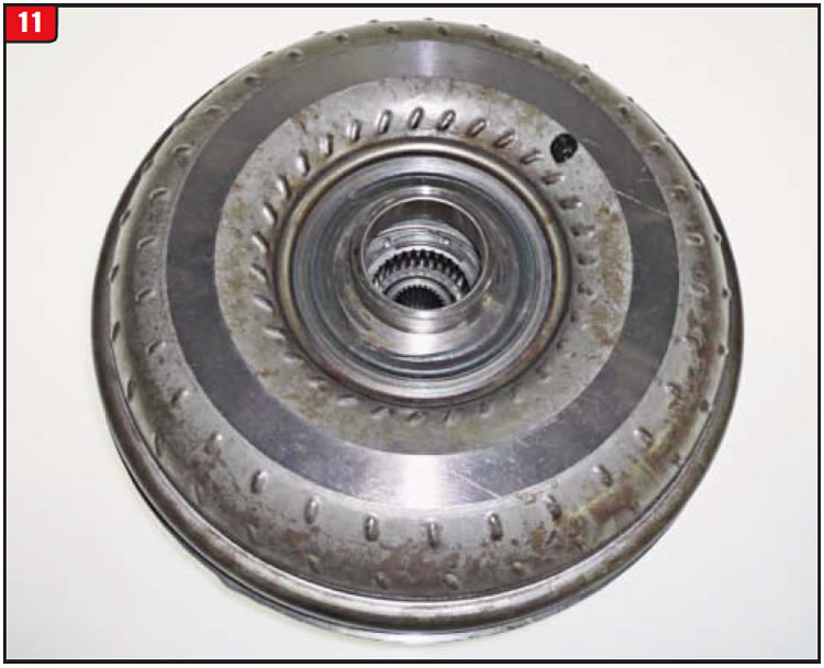
The transmission was inspected for wear etc. and the valve body was given a close look. Overall the unit was in fairly good shape (considering the miles), but the valve body did have a slight amount of wear at one of the key valves. Ultimately, though, it was the torque converter that caused the problem (Figure 11).
There had been several issues with CD4Eʼs since 1994, many of which would stem from the valve body. Certain hard-part damage, such as blowout of the forward/direct-drum snap-ring groove, was a direct result of pressure-regulator-valve wear. Converter-pressure and lock-up-apply problems were also caused by the valve body, mainly due to the converter bypass and converter regulator valve wear.
Although there have been a lot of valve bodies replaced or repaired with oversized valves or kits, not all CD4E failures can be blamed on the valve body. The Tribute engine-stall issue is but one example.
Normally, the torque converter is dumb, meaning it does what the transmission commands it to do. Unless a mechanical lockup occurred within the converter, an engine-kill problem would be due to transmission cross leaks, worn or stuck valves, or electrical issues. A hydraulically induced engine stall, related to just the converter, is a bit uncommon.
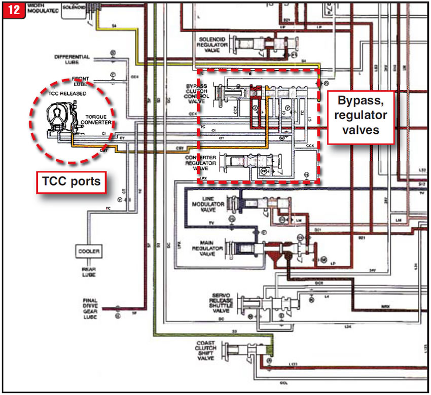
CD4E converter operation is somewhat different from the norm, in that instead of one converter fill (in) port and one converter exhaust (out) port, a CD4E has three ports (Figure 12). In the schematic, the oil passage farthest to the right is a regular lockup-piston off (release) circuit, whereas the center and left passages could apply the lockup piston under certain conditions. All three passages originate from the converter bypass and regulator valves, so if excess wear existed, bad things would happen. It was decided to reuse the valve body, as is, due to what was found in the torque converter.
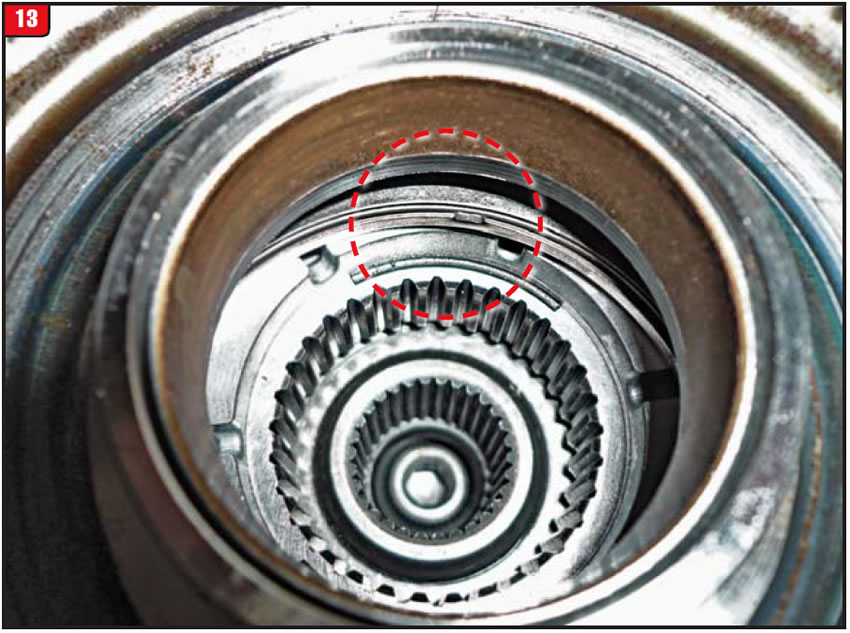
One way to determine whether the converter is causing an engine-stall problem or is on the verge of melting down is to check turbine endplay. Excessive endplay will allow the stator-to-impeller thrust bearing to move out of position (Figure 13). A converter in this condition is one heartbeat away from going nuclear.
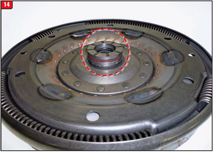
The component responsible for this issue is the turbine. The nose of the turbine will wear down, to the point of allowing the thrust bearing to move out of position. To make matters worse the nose of the turbine hub is notched, to allow release-fluid pressure to spill out in front of the lockup piston and push it back from the cover (release mode). With the turbine hub worn down, the fluid notches are gone and so is the release pressure, allowing the piston to partially lock up when it shouldnʼt (Figure 14). The notches in Figure 14 are all but gone. Replacement hubs are available in the aftermarket.
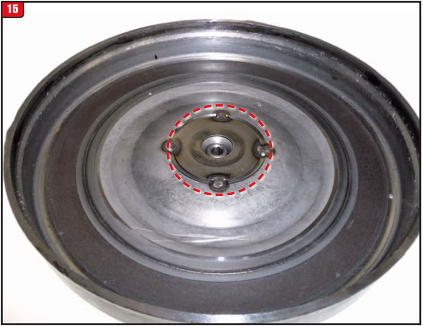
Instead of having a thrust washer or thrust bearing to take the load, the turbine-hub nose is the thrust surface, which contacts a welded thrust plate in the converter cover (Figure 15). This type of wear is showing up more often and will result in additional engine-stall and converter-meltdown issues. Maybe a better design could surface in the aftermarket.
Traditionally, torque converters are blamed for every problem, or so it seems. In this case, however, the converter, not the transmission, was the bad guy.
Special thanks to Chuck Eakin at Jim & Sons Transmission Specialists in Cuyahoga Falls, Ohio, for his contribution to this article.

August 2014 Issue
Volume 31, No. 8
- Jeep 722.6: hard shifting
- 4L60-E: torque-converter fill issue
- CD4E: Mazda Tribute engine stall


