


A transmission that had noticeable damage is repaired. The transmission is thoroughly cleaned, failed parts including the converter are replaced and the cooler lines are flushed. Everything is done correctly.
During or even after the initial road test, the transmission starts to malfunction or may even overheat. Once the pan is removed for inspection, it becomes apparent what the problem is – contamination.
But where did it come from?

Although everything in the transmission and torque converter was cleaned and the lines were flushed, the patient died because of debris that ultimately was not removed from the cooler element. But how is that possible?

There was a time when flushing out a radiator cooler tank and cooler lines was basic and simple. Even if an auxiliary cooler was part of the system it was no big deal – just hook up a flushing machine to the two cooler lines and hit the switch, then reverse the lines and hit it again. Last, unhook one line and, using a blow gun, blast out the excess solvent from the cooler back into the flushing machine. Thatʼs all it took and the job was done, and done right.
Progress, being what it is, touches everything, including cooler systems. Every time the OEMs have made changes in components or systems, potential for disaster exists.
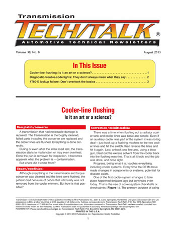
One of the first cooler-system changes to take place happened decades ago but continues even today. That is the use of cooler-system checkballs or checkvalves (Figure 1). The primary purpose of using an inline checkball or checkvalve initially was to reduce torque-converter drain-back. The fitting on the left in Figure 1 is representative of a case fitting with a check-ball. The fitting on the right is an inline fitting, which can be installed on either cooler line, providing it faces in the correct direction.
If the inline fitting is installed backward or the checkball happens to get stuck in the closed position, cooler flow is shut off and the torque converter and even the transmission are toast. Always ensure that any line-fitting check-ball is free and that the fitting is installed in the correct hole or on the correct line.
Another type of cooler-system checkvalve was added to certain transmission models for a different reason. For instance, the Chrysler A604 had a lubrication bypass checkvalve added to it years ago. The checkvalve, which is situated under the pump, is designed to open if the cooler or cooler lines become restricted because of either debris, damage or cold temperature. If it gets cold enough, transmission fluid can gel before the engine and transmission warm up, causing a flow restriction and transmission damage. Under these conditions, the checkvalve will open to allow lube oil to flow inside the transmission.
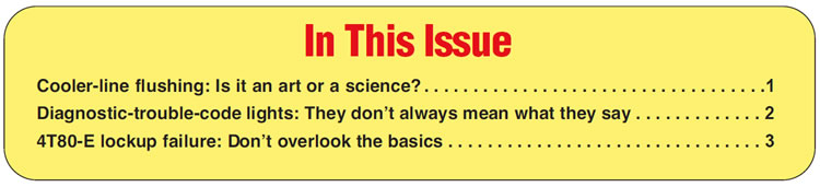
Another example of this type of checkvalve is the bypass line on the E4OD/4R100 transmission (Figure 2). Although this chunk of line functions the same as the A604 lubrication bypass valve, it is more susceptible to problems due to the location. The line, which bolts to the case cooler-fitting holes, is in the direct path of any contaminants generated by the torque converter. E4OD and 4R100 converters have been known to cause just a slight amount of debris; therefore, a good rule of thumb is to replace the bypass line if the converter blows. Just cleaning the radiator cooler doesnʼt help this particular issue.
Beyond cooler lines and fittings is the cooler itself. Here in the U.S. the cooler tank (tube) was always situated in the bottom of the radiator. That was not always the case elsewhere. In Europe, for instance, VW had a different approach on certain models. Instead of sending ATF forward to the radiator, engine coolant was sent back to the transmission to a bolt-on cooler tank (Figure 3).
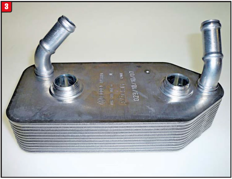
Cooling efficiency aside, this design can also result in a more-difficult means of flushing, because of the compact and restrictive nature of the cooler tank.
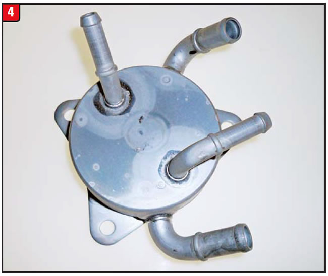
More recently, Honda started to use coolers of this design (Figure 4) on specific models of transmissions. Although Honda refers to its design as a “warmer,” the outcome is the same. Depending on internal damage of the transmission or torque converter, the question remains, at what point does the tank get replaced? The tank can be replaced with a comparable OE design, or another option would be to use an aftermarket adapter and auxiliary cooler in lieu of the OE part. As with the VW design, however, proper cleaning of a contaminated Honda cooler tank is almost impossible.
What about the traditional radiator cooler itself? Donʼt think that the radiator has escaped evolution. Each OEM has taken different approaches over the years. Nissan, for instance, used a type of cooler tube in the radiator that could not be properly cleaned when the transmission had extensive damage. Repeated flushing just would not do it. The cooler tube would have to be replaced.
Ford decided that on certain truck models, the radiator did not need to be part of the transmission-fluid cooling system at all on those particular models. Only a traditional-looking auxiliary cooler was used, becoming an oil-to-air-type cooling system instead of oil-to-water.
In the past several years, though, another variation has taken place. The air-conditioning condenser is now becoming a significant part of the transmission-fluid cooling system. A portion of the condenser cooling tubes is allocated to the transmissionʼs fluid (Figure 5). The condenser in Figure 5 is from a Jeep Commander and is a straight-flow design, meaning that there are no flow restrictions.
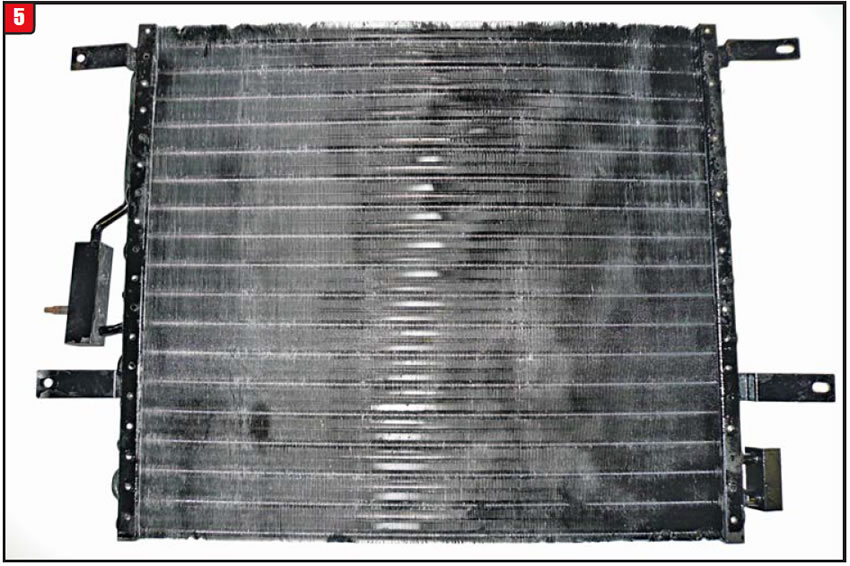
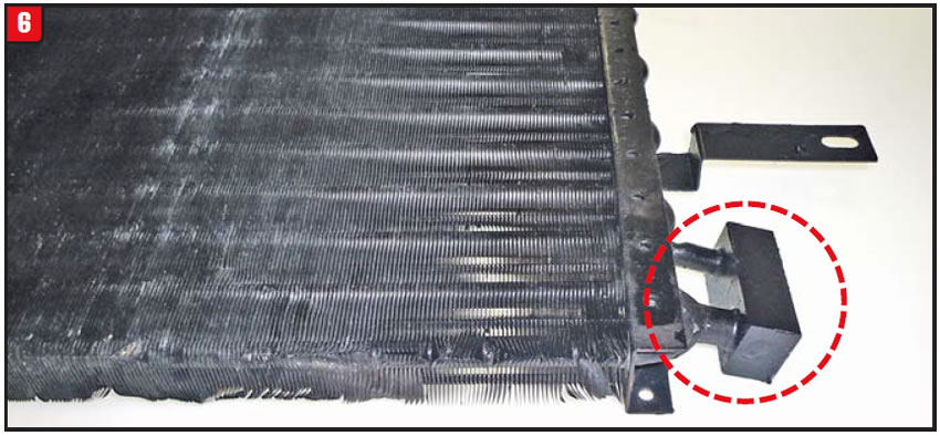
Note: One side of the condenser is the connector block for the A/C, and the ATF connector block is on the other side (Figure 6).
Another deviation that has been causing increasing problems for transmission shops is the use of a thermal bypass valve in some models. To address cooling as well as lube-flow issues, increasing numbers of vehicle applications are being outfitted with the valve.
One example of the thermal bypass design is on the Ford Crown Victoria. Although the A/C condenser for the Crown Vic (Figure 7) looks similar to the Jeep condenser in Figure 5, they are not the same.

The area at the lower-right corner in Figure 7 is where the transmission cooler lines attach but contains the thermal-bypass-valve assembly as well (Figure 8). The purpose of the thermal bypass valve is to control oil flow based upon temperature levels and not flow restrictions.
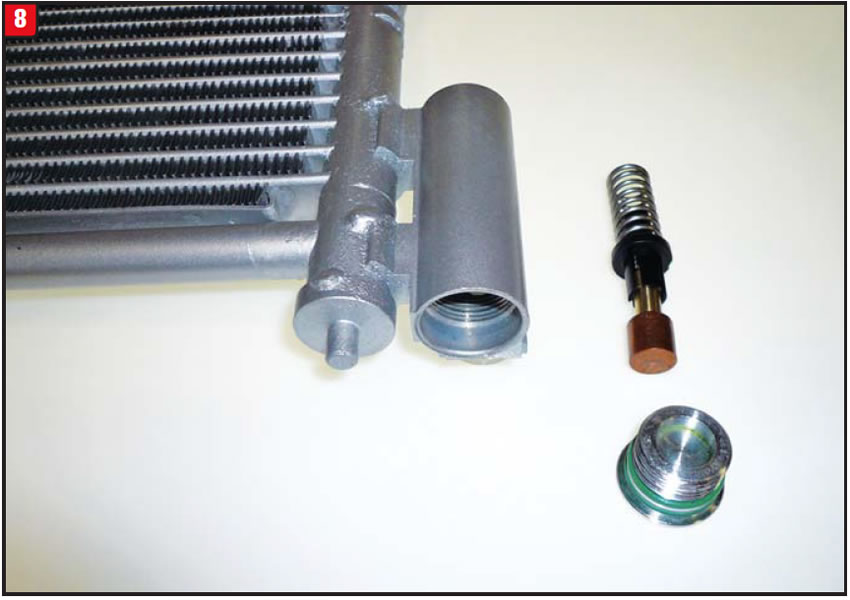
When the fluid is cold, the valve is unseated, allowing fluid to flow from one line fitting to the other, basically bypassing the cooling tubes of the assembly. Flow would be maintained even if the fluid were to gel in the cooler. As the fluid warms up, the thermal valve starts to seal, forcing the fluid through the cooler as needed. A stuck valve in either direction is bad.
The cooler system must be properly flushed as part of a transmission repair, especially if there was significant damage to the unit. Hooking up a flusher to a cooler with this bypass design, at room temperature, accomplishes nothing. The cleaning solvent will mainly bypass the cooler tubes, leaving the crud in the cooler. Either block the valve closed temporarily or make a stationary valve that will cause full cooler flow at all times.
Today, cooler-system flushing, whether it be “an art or a science,” must be performed correctly in order to end with a clean job and good oil flow.
The life of the transmission depends on it.


A 2003 Ford Taurus experiences an erratic DTC light on the dash. The light appears to be a small gear with an exclamation point inside (Figure 9). A P1779 code is retrieved when the vehicle is placed into self-diagnosis.
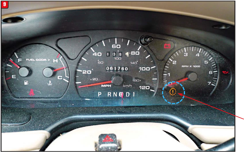
The powertrain control module (PCM) detected a potential problem with the light circuit itself, although the light refers to “check transmission.” There can be more than one cause.
This particular vehicle has a column-shifted transmission, and the PRNDD1 indicator is a more-traditional-looking type. A P1779 code stems from the fact that the PCM has detected a problem with the light, even though the PCM itself could be at fault. Anything in the light circuit can trigger the code, including connections, wiring, terminals or PCM. There is, most likely, nothing wrong with the transmission.
A test procedure needed to be performed to determine the exact cause. There is a white/light-green wire running from pin number 79 on the PCM that controls the light. The wire needed to be disconnected to see whether the light would go out or stay on. If the light goes out by disconnecting the wire, a faulty PCM is indicated, whereas if the light stays on, that indicates a shorted wire etc. The ignition switch needs to be in the run position once the wire is disconnected to verify the results.
Even though a bad wire was the culprit on this vehicle, the question becomes, what if itʼs more? A PCM is costly enough; however, if the instrument cluster is bad, the cost could be even more.
At some point, the customer may just prefer black tape over the light and drive off into the sunset, once they know that the transmission is OK.


A 2003 Cadillac equipped with a 4T80-E transmission, having 81,000 miles, experiences inconsistent lockup. All four upshifts are good, but the unit required two quarts of fluid due to a leak at the cooler line.
Even after the fluid was topped off, the torque-converter clutch would lock but then bump off, as well as set a P0741 trouble code.
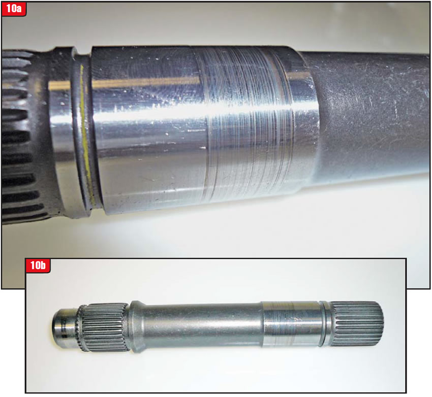
The transmission had wear between the turbine shaft and stator-support bushing and between the shaft and the case cover seal. The converter-hub bushing also had wear.
In an era of transmission and converter problems being attributable to more-exotic component and system failures such as electrical items, invisible valve-body issues and computers, focus should not be shifted away from basics like seals or bushings. Depending on the transmission, a variety of conditions can surface involving decades-old technology, as was the case with the 4T80-E.
The erratic-lockup symptom that the 4T80-E had pointed more toward a sticky valve in the valve body or faulty solenoid than it did toward a constant condition like a worn bushing and journal (figures 10a & 10b).
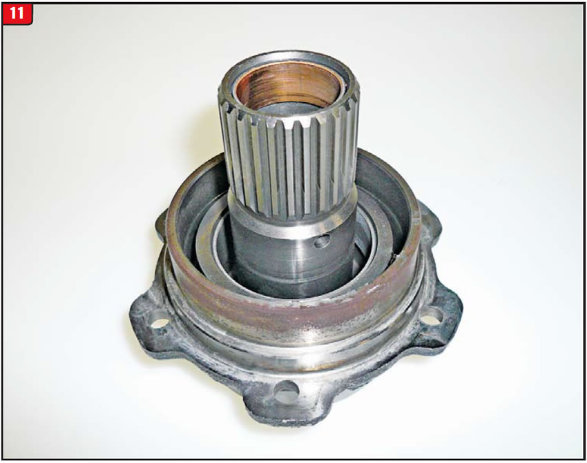
Excessive converter-hub clearance can also contribute to converter-apply issues, without blowing the front seal out of the bore. If, however, the hub clearance allows more flow than the drain holes can handle, the seal will come out (Figure 11).
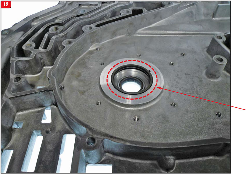
The 4T80-E is unusual when it comes to seals. The turbine shaft is surrounded by seals in order to retain converter oil pressure. The drive sprocket has a solid Teflon sealing ring, but there are actually two metal-clads pressed into the case cover to seal the turbine shaft as well as the back side of the drive sprocket (Figure 12). There is also the good old turbine-shaft O-ring that most GM lockup transmissions have.
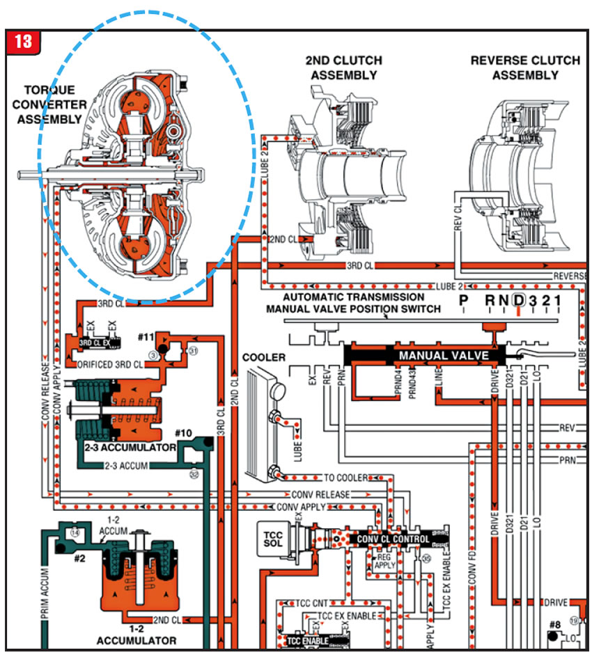
When this type of problem arises, reviewing an oil schematic is always a good idea; however, before homing in on the valves, solenoids and pressure switches, check out the area closest to the item in question (Figure 13).
In the end, diagnosing problems by breaking out the scopes and scanners is great, but “donʼt overlook the basics.”

August 2013 Issue
Volume 30, No. 8
- Cooler-line flushing: Is it an art or a science?
- Diagnostic-trouble-code lights: They donʼt always mean what they say
- 4T80-E lockup failure: Donʼt overlook the basics


