


The 45RFE has gone through many changes since it was introduced in 1999. The pump has had a few changes that pertain to the to-cooler/lube circuit that can cause some overheating and/or planetary-failure conditions if parts are mismatched. The following pages will show these changes in the pump cover and spacer plate, how to identify them, and the interchange information related to them.
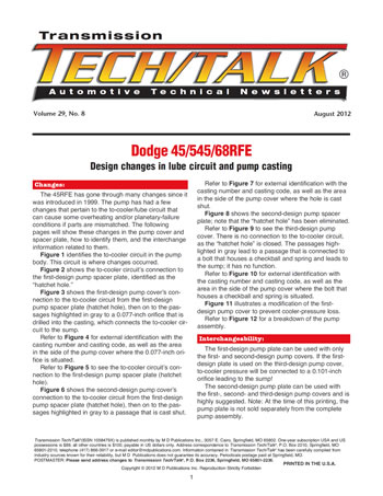
Figure 1 identifies the to-cooler circuit in the pump body. This circuit is where changes occurred.
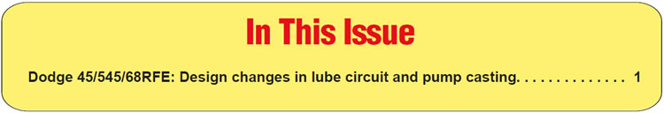
Figure 2 shows the to-cooler circuit’s connection to the first-design pump spacer plate, identified as the
“hatchet hole.”
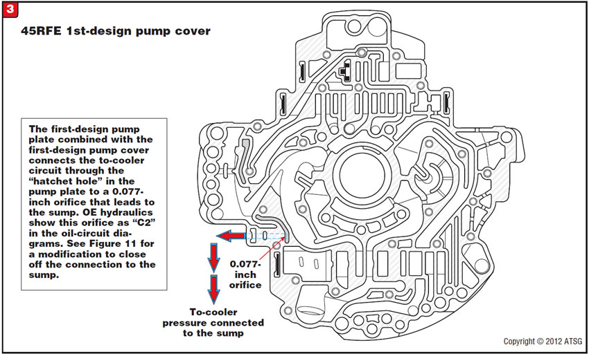
Figure 3 shows the first-design pump cover’s connection to the to-cooler circuit from the first-design pump spacer plate (hatchet hole), then on to the passages highlighted in gray to a 0.077-inch orifice that is drilled into the casting, which connects the to-cooler circuit to the sump.
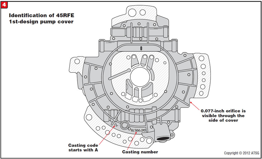
Refer to Figure 4 for external identification with the casting number and casting code, as well as the area in the side of the pump cover where the 0.077-inch orifice is situated.
Refer to Figure 5 to see the to-cooler circuit’s connection to the first-design pump spacer plate (hatchet hole).
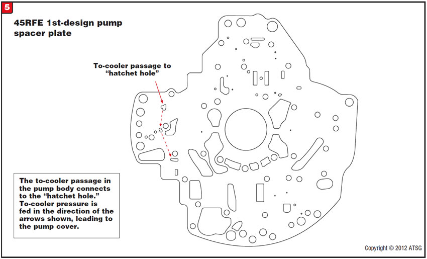
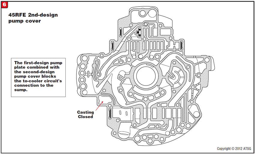
Figure 6 shows the second-design pump cover’s connection to the to-cooler circuit from the first-design pump spacer plate (hatchet hole), then on to the passages highlighted in gray to a passage that is cast shut.
Refer to Figure 7 for external identification with the casting number and casting code, as well as the area in the side of the pump cover where the hole is cast shut.
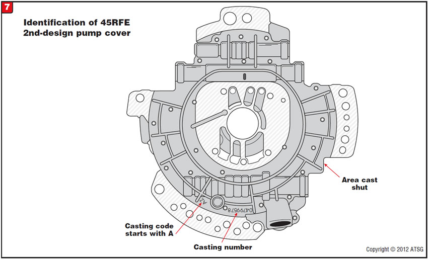
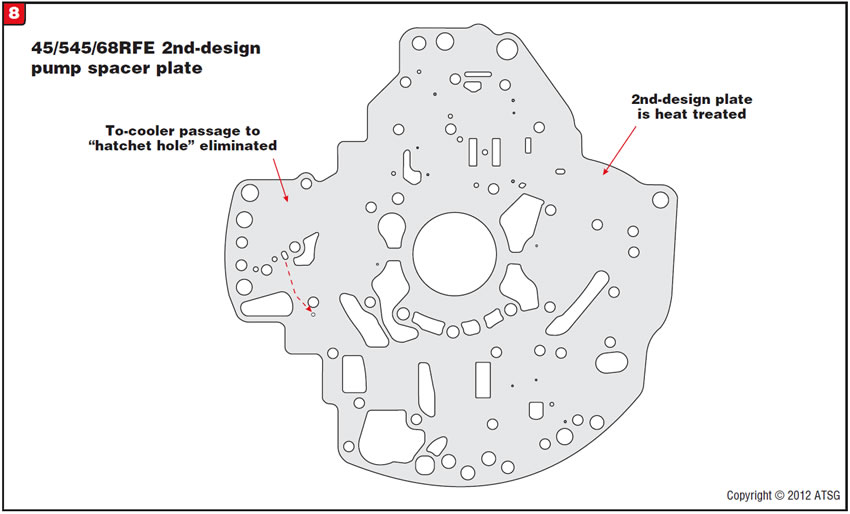
Figure 8 shows the second-design pump spacer plate; note that the “hatchet hole” has been eliminated.
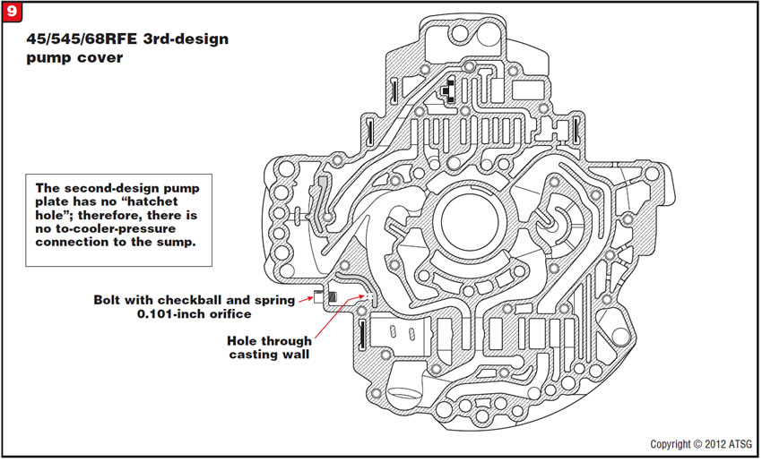
Refer to Figure 9 to see the third-design pump cover. There is no connection to the to-cooler circuit, as the “hatchet hole” is closed. The passages high-lighted in gray lead to a passage that is connected to a bolt that houses a checkball and spring and leads to the sump; it has no function.
Refer to Figure 10 for external identification with the casting number and casting code, as well as the area in the side of the pump cover where the bolt that houses a checkball and spring is situated.
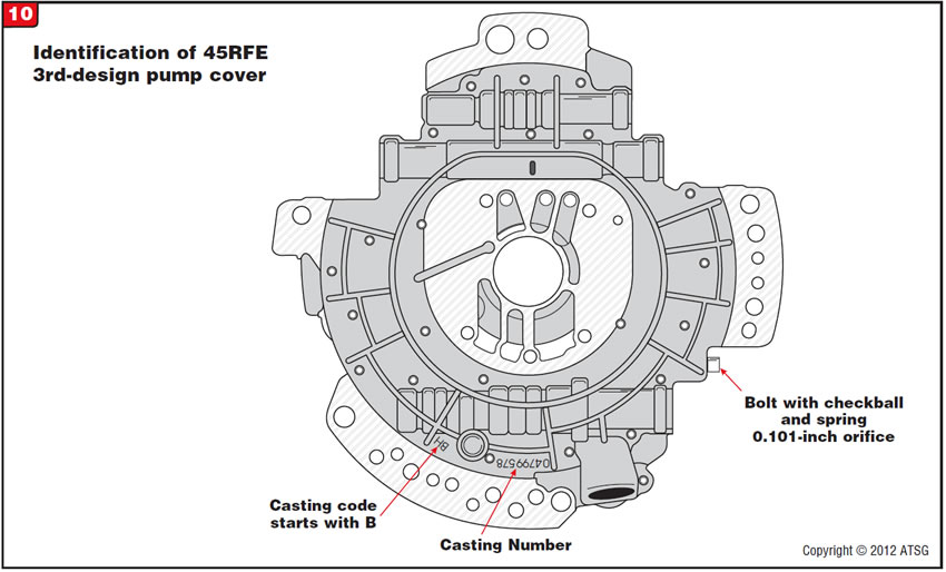
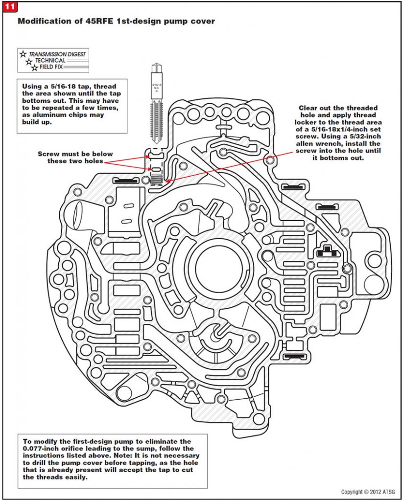
Figure 11 illustrates a modification of the first-design pump cover to prevent cooler-pressure loss.
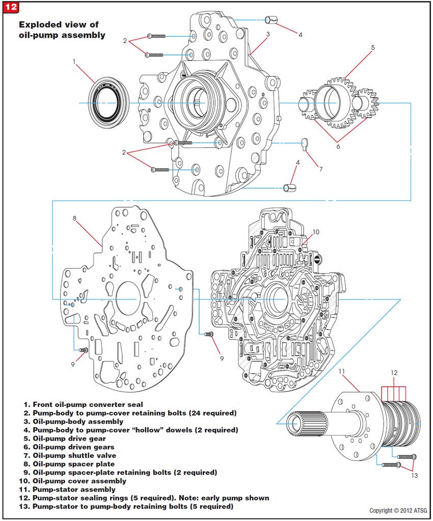
Refer to Figure 12 for a breakdown of the pump assembly.

The first-design pump plate can be used with only the first- and second-design pump covers. If the first-design plate is used on the third-design pump cover, to-cooler pressure will be connected to a 0.101-inch orifice leading to the sump!
The second-design pump plate can be used with the first-, second- and third-design pump covers and is highly suggested.
Note: At the time of this printing, the pump plate is not sold separately from the complete pump assembly.


August 2012 Issue
Volume 29, No. 8
- Dodge 45/545/68RFE: Design changes in lube circuit and pump casting


