
Legal:
The law requires that every new car and light-duty truck sold in the United States be equipped with and support OBD-II (On-Board Diagnostics, phase 2). As a result, the vehicle’s computer or computers must support any one of three designated protocols:
J1850 Variable Pulse Width (VPW)
This has been adopted by GM, which refers to it as Class 2, and by Chrysler, which refers to it as J1850. This is a 10.4-kbps single-wire communication system.
J1850 Pulse Width Modulation (PWM)
This has been adopted by Ford and is known as the Standard Corporate Protocol (SCP) and can be seen in Mazda vehicles as well. This is a 41.6-kbps two-wire balanced-signal communication system.
ISO 9141 and ISO 9141-2 (also known as ISO 9141 CARB)
Seen in some Chrysler and Mazda products but seems to be more common in Europe. This is a 10.4-kbps single-wire communication system.
Chrysler History:
SCI – Serial Communication Interface was Chrysler’s OBD-I 62.5-kbps communication system from 1983 to 1995 (Jeeps 1991-1995). Still in use with 1996 and later vehicles, it is a dedicated high-speed link. It allows communication between a scan tool and the PCM and TCM. Most scan tools communicate with the PCM using this protocol and with the TCM through CCD or PCI.
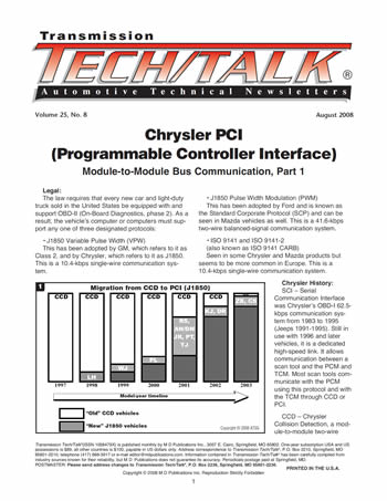
CCD – Chrysler Collision Detection, a module-to-module two-wire 7,812.5-bps bus communication system introduced in 1989 with a phase-out period from 1998 to 2003 (see Figure 1).
PCI – Programmable Controller Interface, a module-to-module one-wire 10.4-kbps bus communication system introduced in 1998 on LH vehicles including the scan tool (see Figure 1). This meets OBD-II J1850 requirements.
PCI Communication
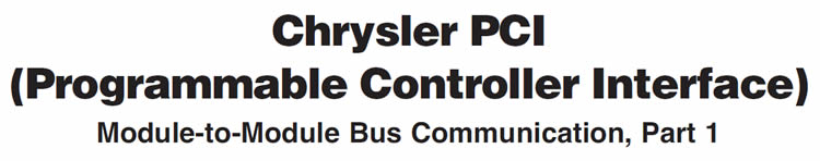
This bus system has the capability of supporting up to as high as 32 different modules. When you monitor voltage on the PCI bus wire, it is normally held low and can be driven as high as 7.5 to 8 volts. In other words, when there is no communication, the system is at rest and will show almost no voltage. This near-zero voltage reading is not an indication that the wire is being grounded, because each module on the system is capable of providing its own pull-up voltage for transmitting data. This means that each module is capable of reading and transmitting bus messages(see Figure 2). SAE International published J1850 VPW DC Parameters, in which we learn that the out-put low-voltage range on the PCI bus wire is 0 to 1.5 volts and the range for the output high voltage is 6.25 to 8 volts. Minimum network resistance can be as low as 315 ohms and as high as 1,575 ohms, depending on the number of modules on the network.
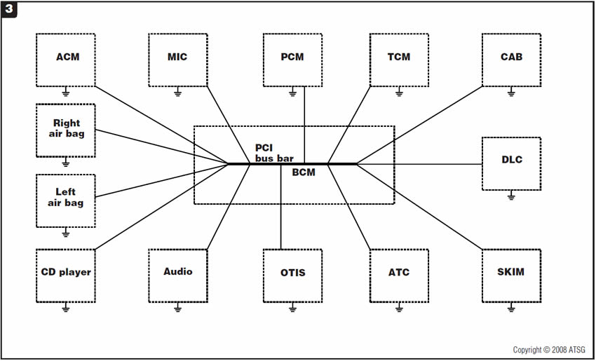
And when it comes to the modules on the network, there are no “slaves or masters” in this communication system, as each module connected to the system can transmit and receive data independently. In some applications the body control module (BCM) is a central connection point for the PCI bus and would be better understood as a “hub.” This does not make the module a master or a slave in the system; it simply serves as a “hub” through which all PCI bus wires pass (see Figure 3).
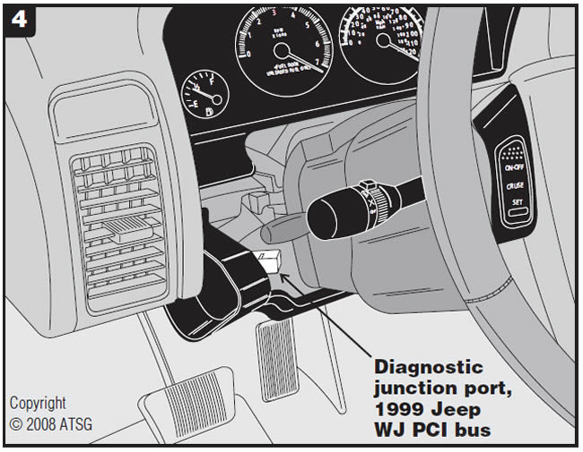
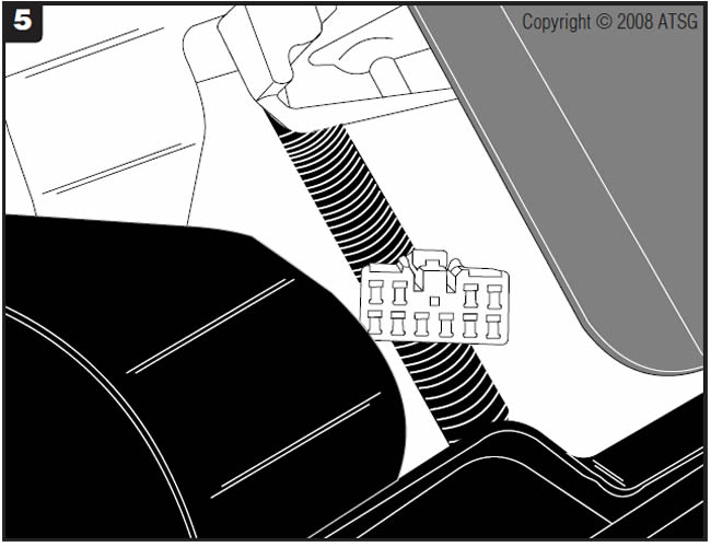
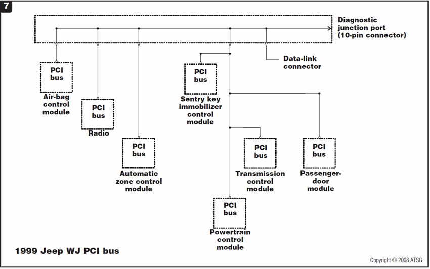
In other applications the central connection point for the PCI bus is a splice known as a diagnostic junction port (see figures 4-7).

Each module that is on the network applies a load to the PCI transceiver circuitry, and since the PCI network can support up to 32 modules (see Figure 3), termination resistors and capacitors are connected in parallel to the transceiver circuit within each module to minimize circuit loading (see Figure 2). What is very helpful is that Chrysler has made available the approximate resistance value of the terminating resistor in each module that could be found on the PCI-network system (see Figure 8).
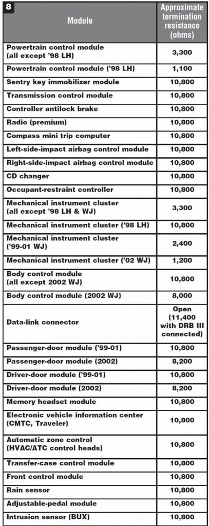
This information, along with the understanding of how each of the modules’ terminating resistor is grounded in the module and that the modules are connected in parallel to each other, allows for an attainable diagnostic approach should the network develop communication errors such as code P1695 (No CCD/J1850 Message from the Body Control Module) or P1698 (No BUS Message from the Transmission Control Module).


A point to consider when diagnosing PCI faults is the Required Fault Tolerant Modes (8.9.1) where the network must meet the requirements as defined per the following failure modes:
- Node (module) power loss – All nodes (modules) must continue to meet the network leakage current requirement during a loss-of-power (or low-voltage) condition.
- Bus short to ground – Network data communications may be interrupted but there shall be no damage to any node (module) when the bus is shorted to ground.
- Bus short to battery – Network data communications may be interrupted but there shall be no damage to any node (module) when the bus is shorted to battery power.
- Loss of node (module) connection to ground –When a node (module) loses its ground connection, the remaining nodes (modules) shall remain capable of communication.
The first diagnostic step is to identify the modules that are on the network of the vehicle being serviced. This can be done with the use of a scan tool or a good wiring diagram like the one provided in Figure 9. This schematic indicates that up to 14 modules can be found on the PCI network, plus the data-link connector (DLC) for the scan tool.
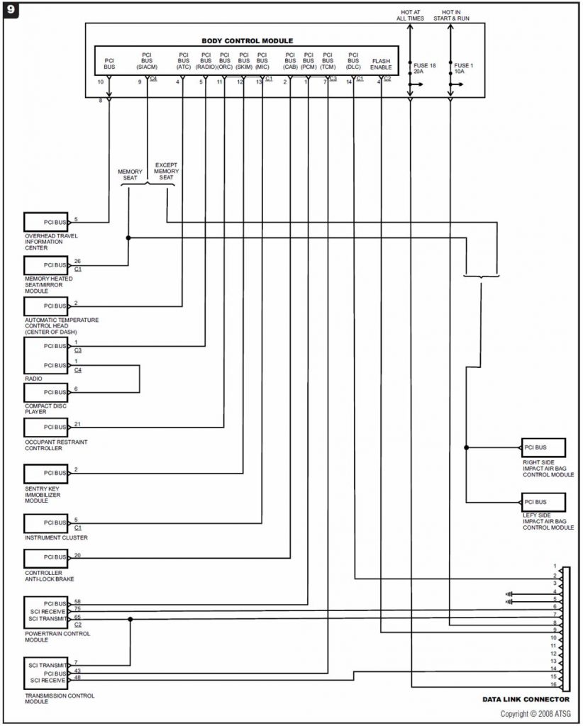
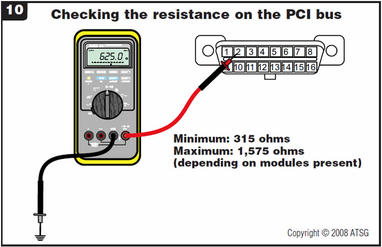
Using the schematic in Figure 9, notice how terminal 2 in the DLC is wired into the BCM at terminal 14 in the C1 connector. If we check this circuit for resistance, according to SAE, the minimum resistance we can expect to see is 315 ohms and the maximum would be 1,575 ohms, depending on the number of modules on the circuit (see Figure 10).
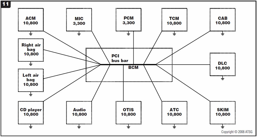
Suppose a vehicle that needs to be tested has 13 modules on the PCI circuit. You determine that there are two modules that contain a 3,300-ohm terminating resistor and 11 that contain a 10,800-ohm resistor
(see Figure 11).
There is a mathematical equation for equivalent resistance in a parallel circuit:

Now if you applied this formula to the two 3.3k and 11 10.8k modules it would look like this:
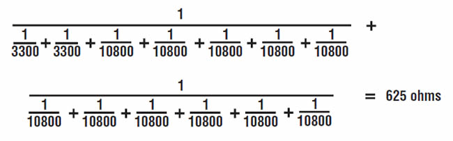
To simplify this equation you could set it up as follows:
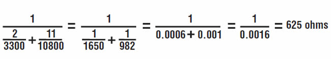
So we have math and theory, and now comes reality: putting the meter on terminal 2 of the DLC as seen in Figure 10, where you should observe 625 ohms if all the terminating resistors in each module are good and every module is grounded. This is a quick way to check the integrity of the circuit, verifying that all modules can be seen on the PCI-bus system.
A short to ground or power takes the entire PCI bus down. A typical technique is to disconnect modules one at a time until the short disappears. With PCI, disconnecting modules doesn’t necessarily have to be the first step. In some instances gaining access to the BCM is very easy, as in a 2001 LH vehicle with the module under the driver-side dash (see Figure 12).
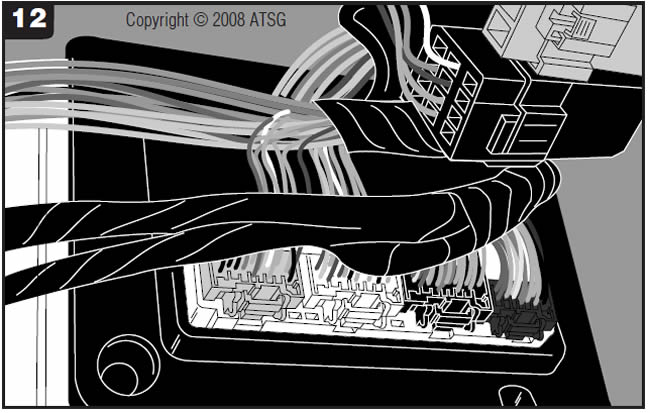
Four of the connectors are very easily accessed; the fifth is a bit more difficult as it is between the junction block and the back side of the BCM (see Figure 13).
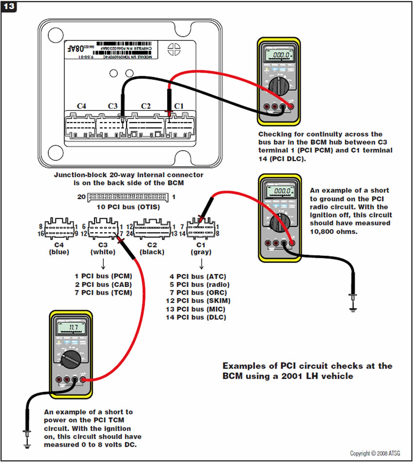
Figure 13 identifies each connector that plugs into the BCM and which connector contains PCI circuits that run through the BCM’s bus bar. Figure 13 also shows an example of making a continuity check across the bus bar inside the BCM and making individual PCI circuit checks with these connectors unplugged from the BCM. A bad BCM bus bar can be quickly and easily diagnosed with a DVOM, as can any shorts to ground or power on individual PCI circuits. This is a much-faster diagnostic step than the typical technique of disconnecting modules one at a time until the short disappears.


August 2008 Issue
Volume 25, No. 8
- Chrysler PCI(Programmable Controller Interface) – Module-to-Module Bus Communication, Part 1


