


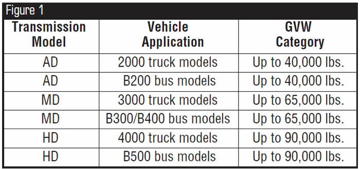
Allison World Transmissions are fully computer-controlled transmissions that come in three truck models and four bus models. The model designations are AD, MD and HD, and each is rated for different gross vehicle weights (GVW).
The following information indicates which GVW categories they fall into and what the abbreviations following the transmission model number mean. The chart in Figure 1 indicates the model designations, vehicle applications and GVW categories.
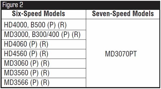
The chart in Figure 2 indicates model designations for six- and seven-speed models.
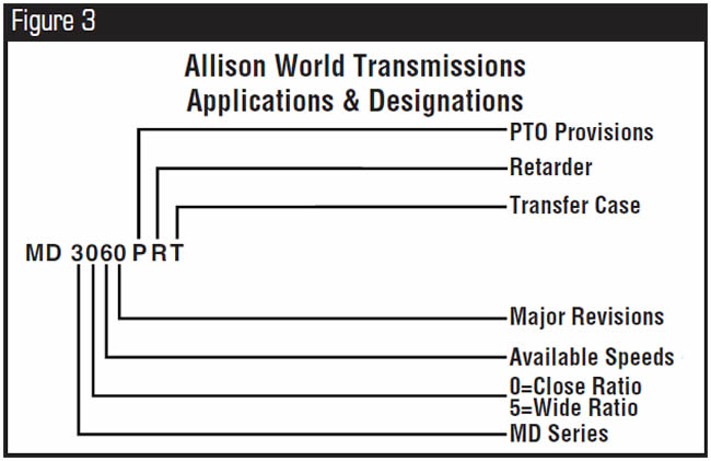
The charts in figures 3 and 4 indicate the meanings of model-designation abbreviations.
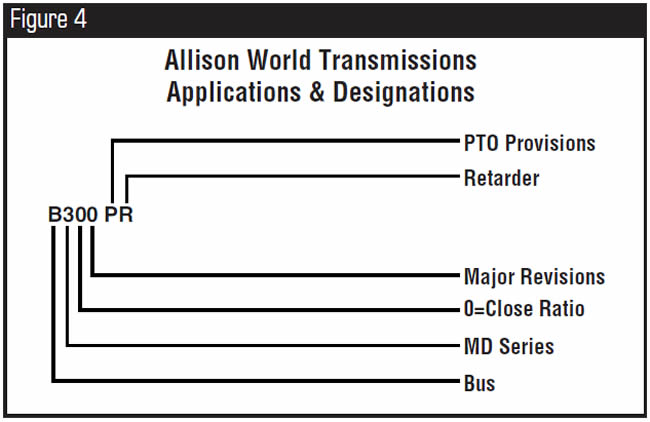
NOTE: The letters RM following the transmission model number mean it has been remanufactured.


The technician is unable to retrieve codes on vehicles equipped with computer-controlled Allison World Transmissions such as 3000, B300/B400 Series, and 4000 and B500 Series transmissions etc.

A lack of diagnostic equipment available to the aftermarket to successfully communicate with the computer control systems in the various vehicles that are equipped with the Allison World transmissions.

There is a manual procedure for retrieving codes on vehicles equipped with these transmissions. The meaning of the display once you have initiated the code-retrieval sequence can be somewhat confusing without clarification.
The code-retrieval procedure will vary depending on whether the vehicle is equipped with a shift lever or a keypad shifter and whether the transmission is equipped with an oil-level sensor. The “flash code” display also will differ depending on whether the shifter has a single- or double-digit display.
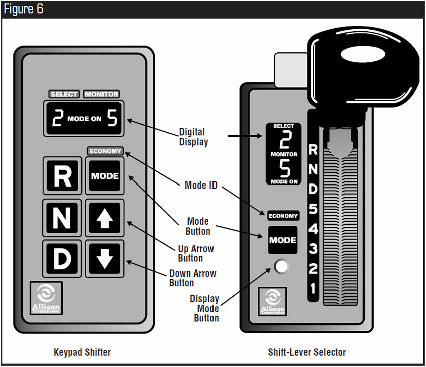
Figure 5 illustrates shifters with single-digit displays, and Figure 6 shows shifters with double-digit displays.
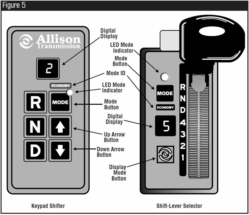
When an active diagnostic code is stored, the LED indicator next to the mode button will be illuminated on vehicles with a shifter that has a single-digit display.
On vehicles having a shifter with a double-digit display, the “Mode On” light will illuminate. At this time the transmission may be in limp mode.
Note: To initiate the code-retrieval sequence on models with keypad shifters, press the up and down arrow buttons simultaneously. On models with shift-lever selectors, press the Display Mode button once.
If the transmission is equipped with an oil-level sensor and you perform the preceding procedure, you will not be in the code-retrieval mode; you will be in the oil-level-information mode.
To skip the oil-level-information mode, press the up and down arrow buttons or the Display Mode button twice. You will now be in the diagnostic mode.


Once you activate this mode, a two-minute countdown begins if the following conditions exist:
- Engine is at idle
- Sump oil is at operating temperature
- Transmission output shaft is stopped
- Transmission is in neutral
- Oil-level sensor is functioning properly.
Oil level will be displayed at the end of the two-minute countdown. During the countdown, the display will begin to flash the numbers 8, 7, 6, 5, 4, 3, 2, 1, with the numbers decreasing by one digit every 15 seconds.
Failure to meet any of these conditions will stop the two-minute countdown, and an oil-level code will be displayed. The two-minute countdown will resume where it stopped once all the conditions are met.
Shift selectors with single-digit display will display the four-digit codes one digit at a time. Shift selectors with double-digit displays will display two digits at a time.
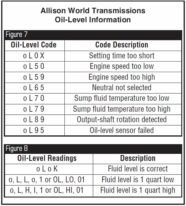
The chart in Figure 7 shows oil-level codes. Once oil-level-information conditions are met, the shifter display window will display the oil-level information, as shown in Figure 8.
To exit the oil-level-information mode, on keypad shifters, either press the neutral button twice or simultaneously press the up and down arrow buttons twice.
On models with shift-lever selectors press the Display button twice, or momentarily move the shift selector to any range and then back to the neutral position.
Important Note:
To bypass the oil-level-information mode, on vehicles equipped with the keypad shifter, you must press the up and down arrow buttons simultaneously twice.
On models with shift-lever selectors, you must press the Display Mode button twice.

To enter the code-retrieval mode on models with keypad shifters and no oil-level sensors, press the up and down arrow buttons once; if the unit has an oil-level sensor, press the buttons twice.
To enter the code-retrieval mode on models using a shift-lever selector and not equipped with an oil-level sensor, press the Display Mode button once; if the unit has an oil-level sensor, press the buttons twice.
If no codes are present, the display will show a dash (-) on shifters with single-digit displays and a double dash (—) on shifters with two-digit displays.
If codes are present, the display will show first the two-digit “Code List Position,” followed by the two-digit “Main Code,” followed by the two digit “Sub-Code,” as shown in the following example: Code List Position, d1; Main Code, 25; Sub-Code, 11.
This means that in the D1 shift position, code 25 for an output-speed sensor was stored and sub-code 11 for zero mph in first gear was stored.
Each digit is displayed for about a second, and the cycle will repeat itself whenever the Mode button is pressed.
To view codes in the d2, d3, d4 or d5 position, momentarily press the Mode button once. When the fifth-position codes are displayed, pressing the Mode button once will restart the sequence, displaying codes stored in the d1 position.
Clearing Codes
While in the diagnostic mode, push and hold the Mode button for about 10 seconds to clear all stored codes.
Shift-selector models with double-digit displays will sound a tone in eight seconds and another tone in about 10 seconds, indicating “All Clear.”
Shift-selector models with single-digit displays flash the LED indicator three times after about three seconds and three times again after about 10 seconds, indicating that all codes have been cleared.
Exit Diagnostic Mode
On models with keypad shifters, press the Neutral button or simultaneously press the up and down arrow buttons once.
On models with shift-lever selectors, press the Display Mode button or move the shift lever to any range and then back to the neutral position.
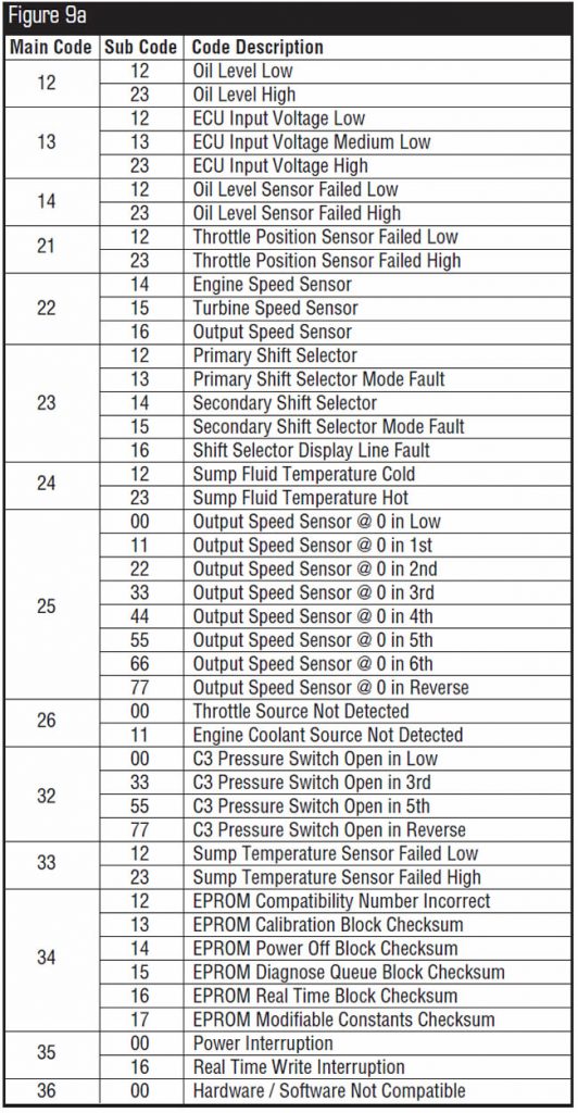
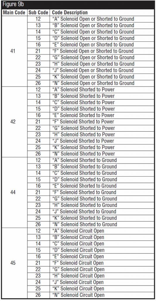
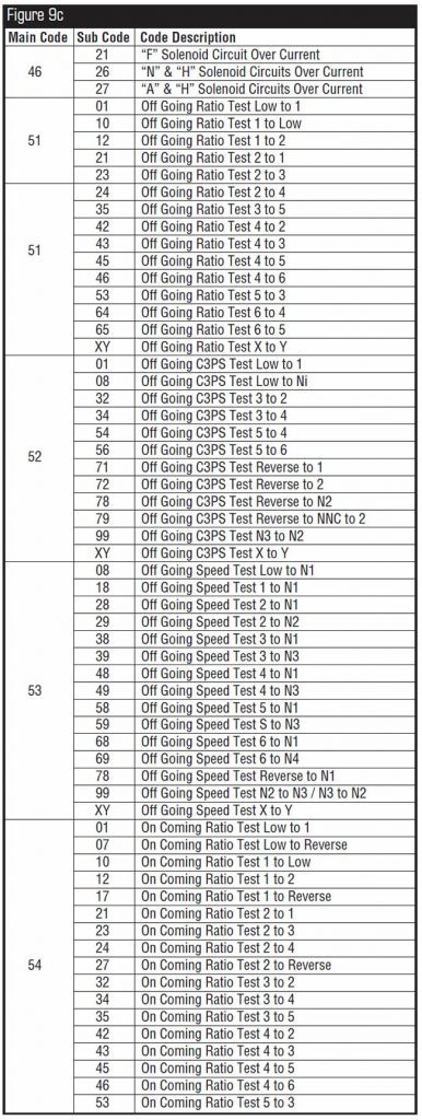
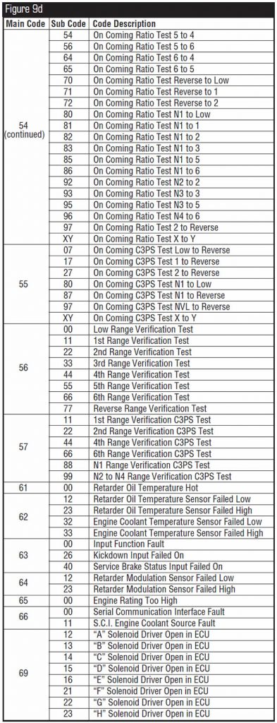
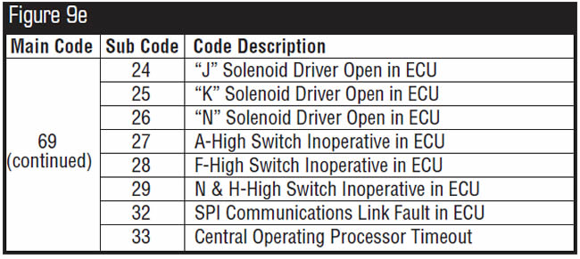
The charts in figures 9a to 9f provide a list of main codes and sub-codes.


After overhaul the transmission binds up on the 1-2 shift; initial take-off in first and reverse have no complaints.
The first clutch has been assembled incorrectly and is causing these complaints. The order of the friction and steel plates in relation to the rear ring gear can be confusing even with a factory manual.
Without the correct clutch/steel arrangement, the first clutch is jammed on mechanically.
Since the first clutch is used with the fourth clutch to attain reverse, there is no reverse complaint. Nor is there a complaint on initial take-off, because the first clutch is applied with the forward clutch. But once the transmission attempts a 1-2 shift, the first clutch cannot release, resulting in a bind-up on the 1-2 shift.
Place the rear ring gear on the workbench with the extended teeth down, as shown in Figure 10.
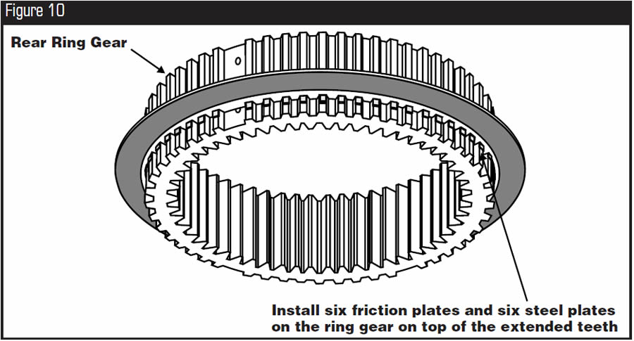
Load six steel plates and six friction plates onto the ring gear. Grasp the entire ring gear and clutch-pack assembly and turn it upside down so the extended teeth are at the top of the clutch pack, as shown in Figure 11.
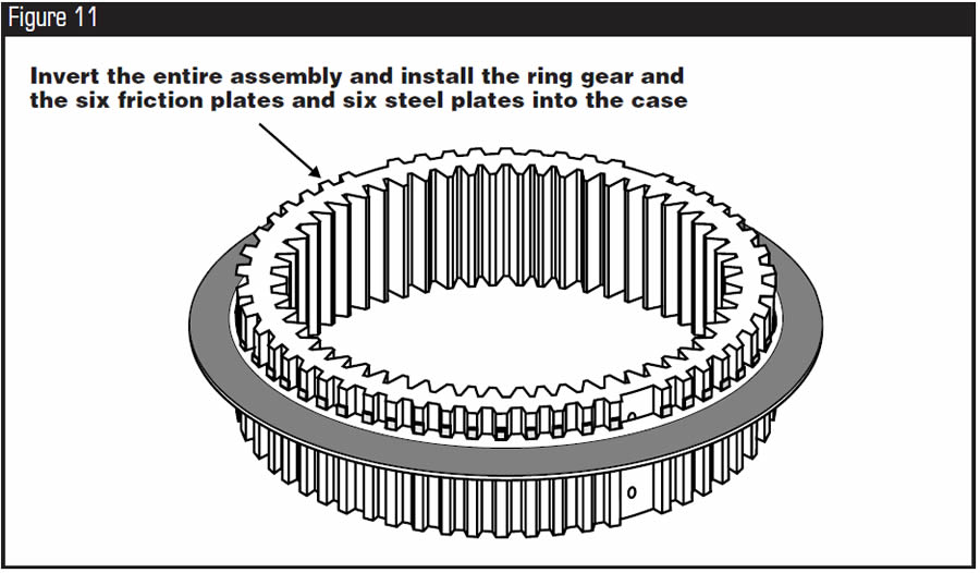
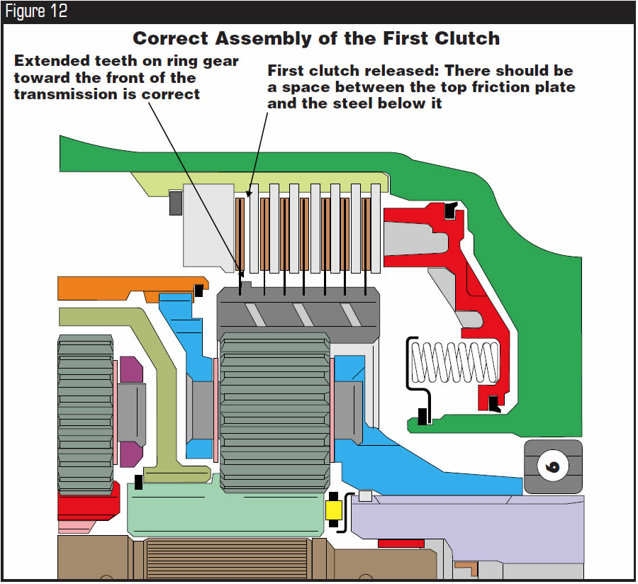
Now, install the assembly into the case, using care to align the external tabs of the steel plates with the slots in the case. Then install the last steel plate and then the last friction plate, so that it is sitting on top of the extended teeth of the ring gear, followed by the pressure plate and snap ring. Refer to Figure 12 for the correct assembly of the first clutch and ring gear. Figure 13 shows incorrect assembly of the first-clutch pack and ring gear.
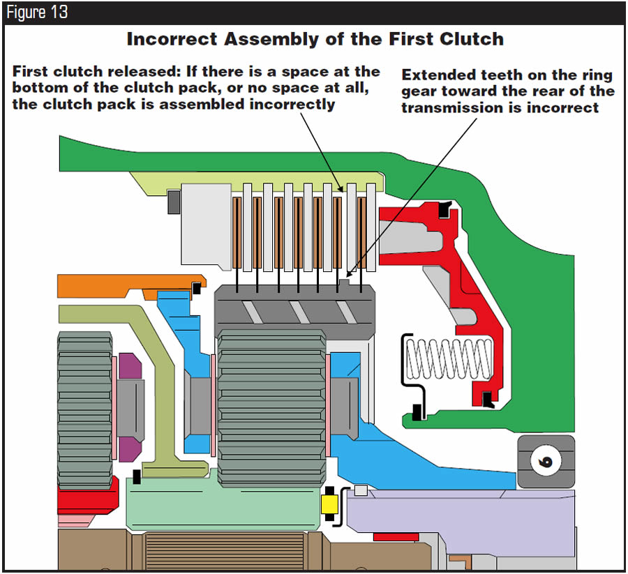

This procedure is necessary on 500-series transmissions after serial number 5071. Before 5071 units, the ring gear did not have extended teeth. 5071 is the last four digits of the serial number.
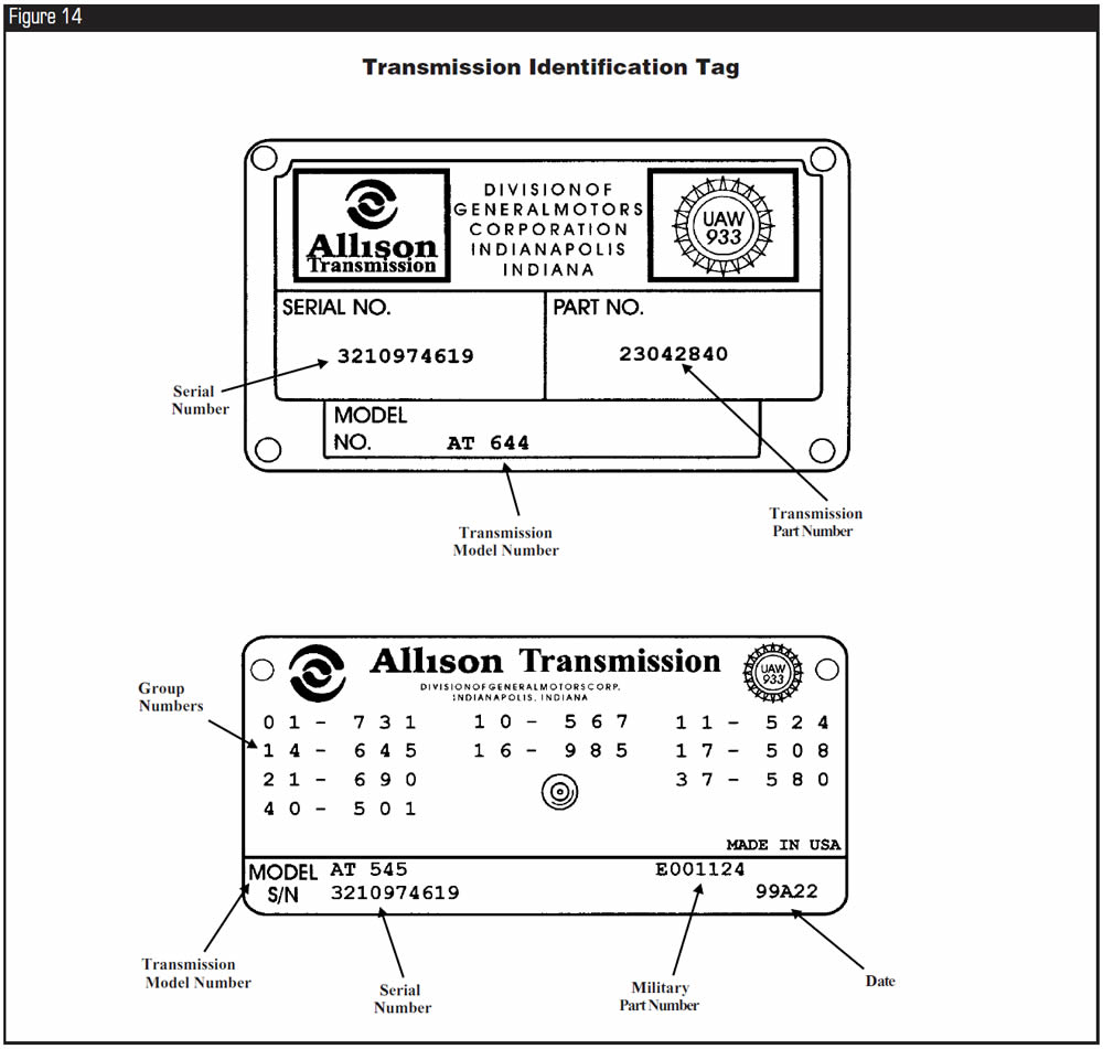
All Allison transmission identification for parts and service needs is on the identification tag on the transmission case (see Figure 14). To receive the correct parts and technical information, you must have the transmission serial and model numbers and part number.

August 2004 Issue
Volume 21, No. 8
- Allison World Transmissions: Applications & Designations
- Allison World Transmissions: Manual Code-Retrieval Procedure
- Allison World Transmissions: Oil-Level-Information Mode
- Allison World Transmissions: Code-Retrieval Mode
- Allison 500 Series Transmissions: Incorrect Assembly of the First Clutch


