

As the race toward infinite gear ratios continues, transmission manufacturers search for better ways to meet all the OEM requirements. Traditionally, more gears meant more stuff; however, with new technologies, attaining the goal of doing more with less is much easier. Computer strategies have also contributed to improved drivability of a vehicle having seven, eight or more gear ratios.
The first company to launch an eight-speed automatic transmission was Aisin. The AA80-E uses six clutch packs, but only two planetary gear sets. The ZF 8HP family of transmissions has only five clutch packs; however, they contain four planet sets, all simple gear type. The layout of the unit is
compact.
There are several different models of the 8HP, depending on capacity. They currently range from the 8HP30 to the 8HP90. The 8HP30 through 8HP45 could be considered small, lighter-duty models, whereas the 8HP55 through 8HP90 are larger and heavier-duty units.


The customer base using the 8HP has been expanding, beginning in 2009 with BMW (of course) up to Audi. With the start of 2012, Chrysler added the line. Initially, Chrysler bought the 8HP45 from ZF but in 2013 started to manufacture its own version of the design called the 845RE. At least currently, Chrysler will use the ZF 8HP70 for models with larger engines, because of volume.
The 8HP has a first-gear ratio of 4.696-1, a sixth-gear ratio of 1-1 and eighth-gear ratio of 0.667-1, which is a pretty good spread. The transmission was designed to have low drag, by applying as many frictional elements at one time as possible. At any given speed there are three of the five clutch packs applied. The torque converter is a twin torsional design for better drivability and NVH (noise, vibration and harshness) and uses a captive clutch for lockup. The fluid required by ZF is the Lifeguard 8 type.
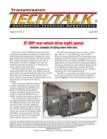
The 8HP is a one-piece case design with one electrical case connector to accommodate all electrical activity (Figure 1). The transmission illustrated is an 8HP45 and has a cooler tank of rather elaborate design bolted to the side of the case. Not all models use this design. Although this model has an output-shaft flange for 2WD, the case can accommodate AWD vehicles. The torque converter is also unusual in that it has a drive plate welded to the front of the converter and the hub has splines for the pump gear instead of flats or notches.
Many of the bolts used for the 8HP are light-weight aluminum/magnesium-type bolts, which may need to be replaced during reassembly. Disassembly of an 8HP is not too bad. Remove the output flange, pop the pan, remove the bolt for the electrical-connector bracket and lift to remove the connector. Unbolt and remove the valve body and tubes, then unbolt and, using a screwdriver, remove the pump assembly. Once this is done, the rest of the gear train will literally fly out of the case.
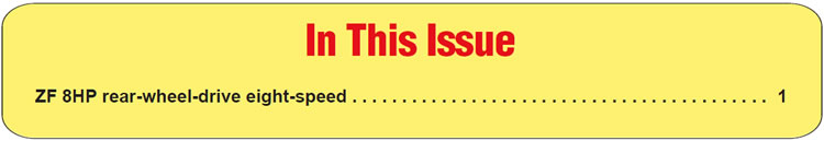
The first component to look at is the pump (Figure 2). The 8HP pump is rather unusual for a couple of reasons. First, unlike previous ZF transmissions, the 8HP uses a remote (off-axis) pump rather than direct drive, and second, the pump itself is sandwiched between the front cover and stator support, almost hidden. There is a drive/driven-sprocket set and chain as in a 6T70, but the drive sprocket has splines to mesh with the converter hub, not drive lugs. The pump cover uses an O-ring, no gasket.
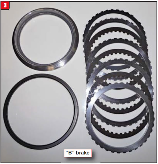
The back side of the stator support houses the two stationary brakes. The small cavity is for the A brake; the larger cavity is for the B brake. The B-brake retainer merely sits onto the stator.
Of the two stationary brakes, the B brake (Figure 3) is larger in diameter and is applied in first gear through fifth gears and reverse. The piston is aluminum but the retainer is bonded rubber and metal. One thing to note: There is no piston return spring, so donʼt look for one. The piston seals on this and other clutch pistons are unusual in that they look like micro lip seals with a base. The B brake has a cushion spring and splines to the #1 planetary ring gear.
The remaining stationary brake is the A brake and is the smaller of the two (Figure 4). The A brake is applied in first, second, seventh, eighth and reverse. There is only an apply piston and return spring, no bonded retainer. The A brake also has a cushion spring for apply.
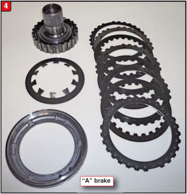
The hub for the A brake splines to the #1 and #2 planetary sun gear, which is a common sun gear. There are thrust bearings and races on both sides of the hub.
The first planetary set in the lineup –call it #1 (for lack of a better phrase) – is splined to the front end of the long drive shell (Figure 5a). At the other end of the drive shell is the #4 ring gear, which is therefore driven by planet #1. The #1 planet shares the common sun gear with planet #2. The ring gear in this set has a hub that is staked into position and not replaceable.
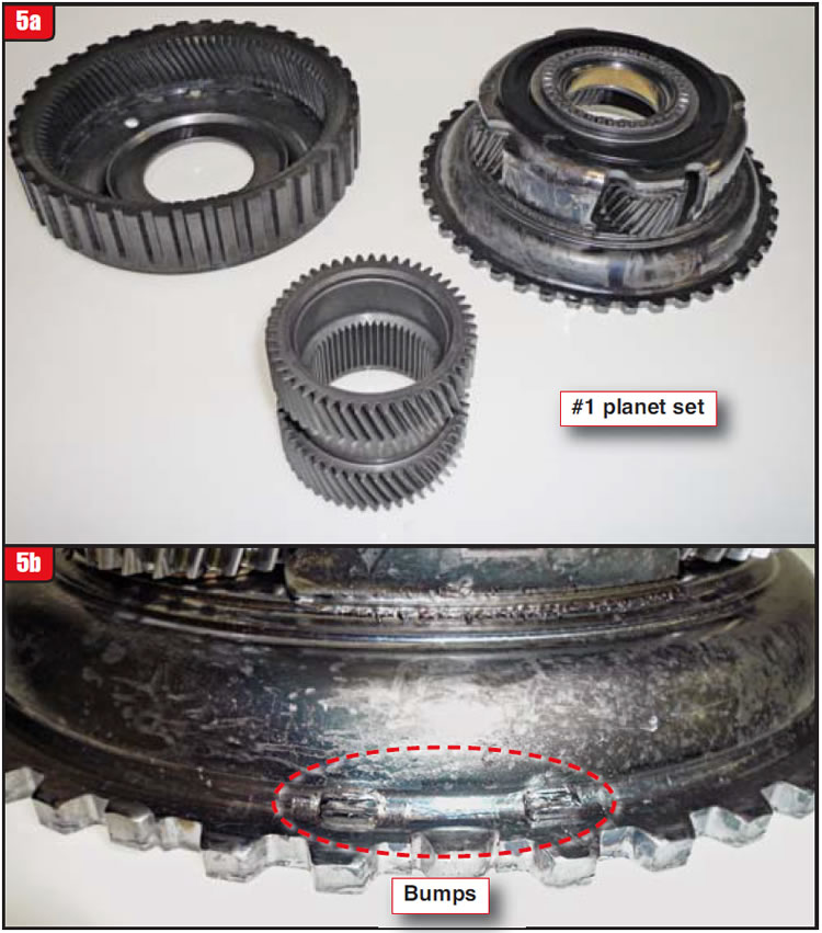
The #1 planet-to-shell snap ring is one of two that can be difficult to remove. There are three bumps on the planet to prevent the snap ring from popping out or rotating (Figure 5b). It is necessary to gently pry inward on the snap ring while lifting the snap ring over the bump. Pry too hard and the shell will break – big problem.
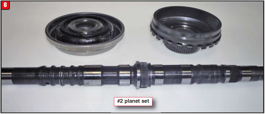
The #2 planet set is next in line (obviously) and is splined to the input shaft (Figure 6). The bearing race must be removed to get the shaft-to-planet snap ring off. The #2 planetary ring gear is also mated to the #3 planetary sun gear. The input shaft has several sealing-ring grooves as well as O-ring journals, which must be inspected closely.
The #3 planetary carrier is aluminum, unlike the others, possibly because it splines to the short drive shell, which is also aluminum (Figure 7a). As stated previously, the #3 planet sun gear is splined to the #2 ring gear, whereas the ring gear for the #3 gear set splines to another shell that has the #4 sun gear attached (the ankle bone connected to the shin bone).
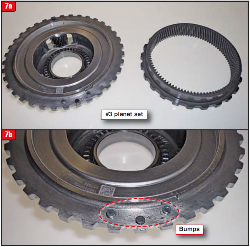
The #3 planet-to-shell snap ring is the second teeth-clinching snap ring to remove. The planet carrier also has bumps on it like the #1 planet carrier (Figure 7b). Again, use caution when removing the snap ring to avoid cracking the shell.
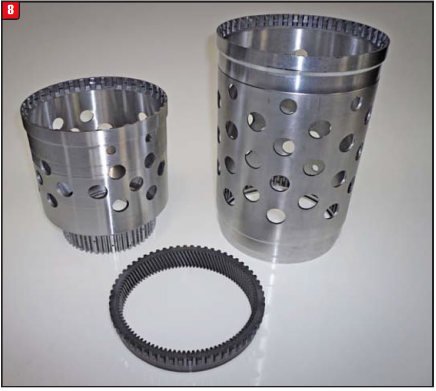
It took a lot of guts for ZF to develop and rely upon the two aluminum drive shells. The shells are long and thin (lightweight) and bear the torque load of the vehicle (Figure 8). The long (outer) shell, which looks like Swiss cheese, has the #1 planet splined at one end and the #4 ring gear splined at the other end. The short (inner) shell has the #3 planet splined at one end but has the D-clutch hub cut into the other. They are probably somewhat costly if damaged.
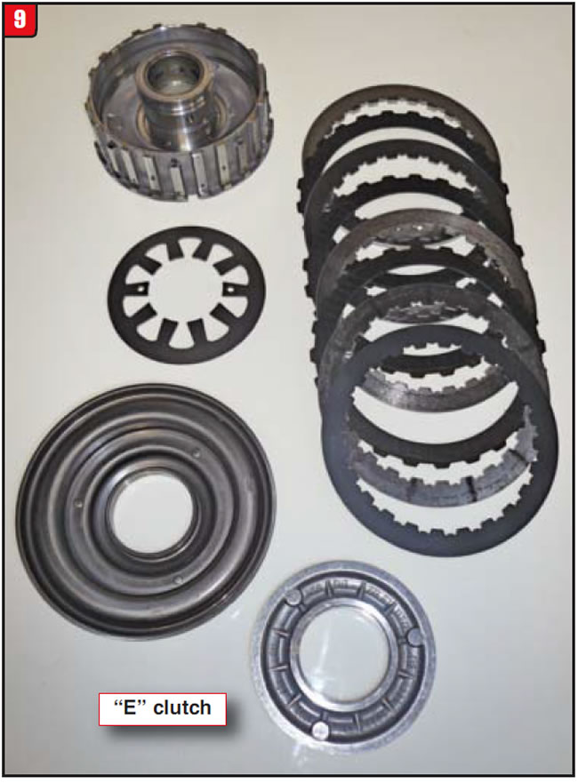
The first rotating clutch in the stack-up is the E clutch (Figure 9). The E clutch is applied in second, third, fourth, sixth and eighth gears. The E clutch is kind of a backward-operating clutch assembly. The apply piston and return spring are set into what would normally be considered a clutch hub. The frictions, which have external teeth, mesh with the sun-gear shell, not a drum. The apply piston actually pushes away from the retainer to apply the clutch. The E clutch also has a cushion spring.
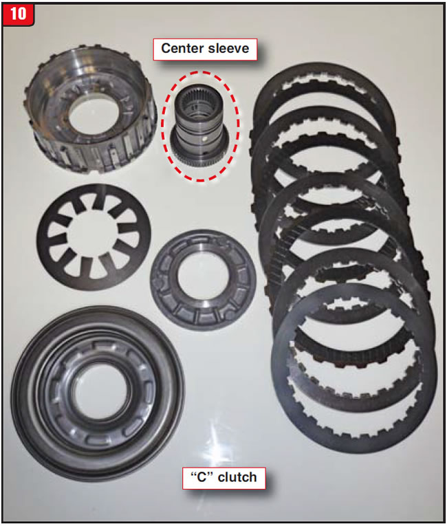
Although the next rotating clutch looks like a carbon copy of the E-clutch assembly, there are a couple of differences. The C clutch does, however, operate like the E clutch (Figure 10). The C clutch is applied in first, third, fifth, sixth and seventh gears. The frictions and steels are the same as in E, whereas the hub and center sleeve are different. The C-clutch assembly also resides in the #4 sun-gear shell, just deeper. The steel center sleeve splines to the hub as well as to the input shaft, toward the back end.
The last planetary set in the 8HP is #4 and is the most complex. Not only does it consist of a planetary carrier, sun gear and ring gear but it also has the output shaft attached, as well as the D-clutch drum assembly (Figure 11). The D clutch is applied in fourth through eighth gears and reverse. The #4 sun gear is the one with the attached driving shell that contains the C and E clutch assemblies. Obviously, driving shells are a big thing on the 8HP, since there are three long ones in the unit to transfer torque.
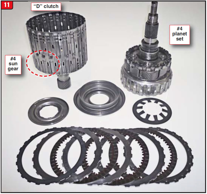
The issue with dealing with the #4 planet has to do with disassembly and reassembly of the D clutch. The first thing to note is the piston retainer; there is no snap ring. The retainer actually pushes downward over notches on the center hub and is then twisted slightly to lock it in position. There are two holes in the retainer for the tool to do it. The #4 planet also has the output reluctor as part of it. The D clutch uses a cushion spring like the other clutch packs.
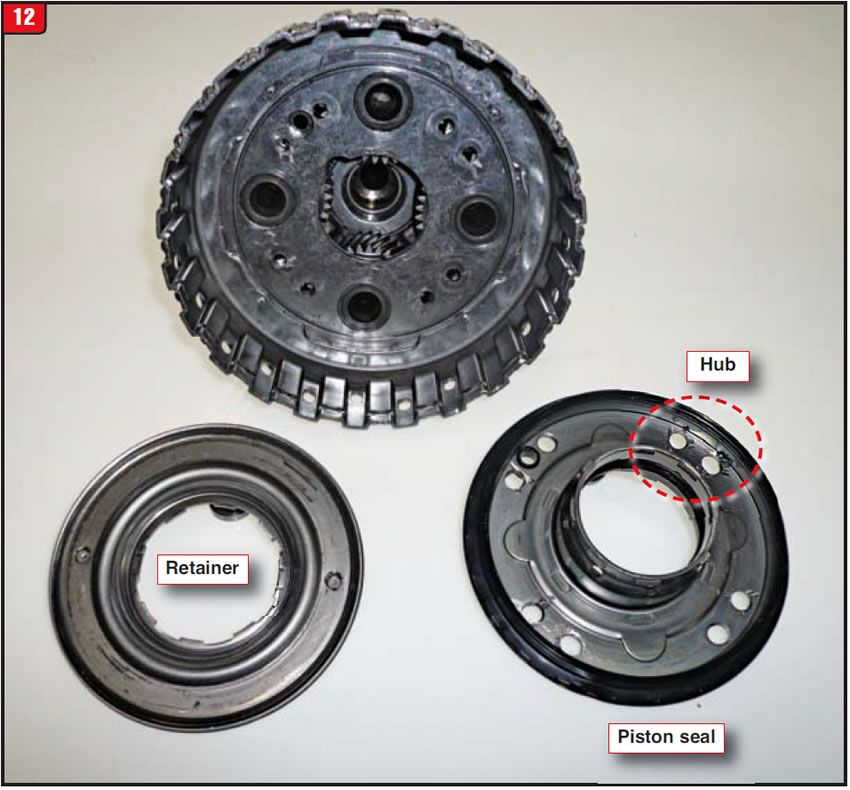
The most-difficult issue to deal with on the 8HP has to do with the removal and replacement of the D-clutch piston seal. The piston seal is actually riveted to the planet carrier (Figure 12). To remove the seal, the heads of the rivets must be drilled out; then, once the seal assembly is removed, the rivet shank also gets drilled out. Use caution to not drill too deep. Currently, there is not a service kit available; however, it is in the works. Also shown in Figure 12 is the center hub, which locks the piston retainer to the riveted piston seal.
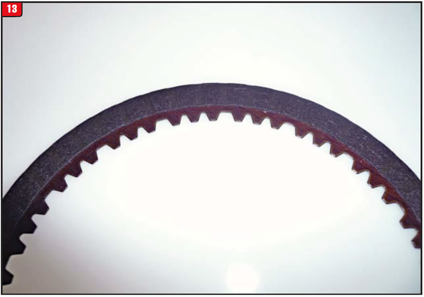
One other issue concerning the D clutch is the D-clutch friction. Usually, friction-plate teeth are uniform. The 8HP D friction is not. There are teeth with a V cut but others that are square cut (Figure 13). This may be due to the D-clutch hub, which is cut into the end of the short aluminum drive sleeve, to prevent wear.
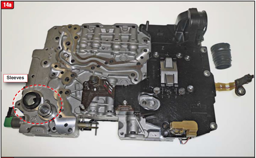
The valve body used for the 8HP family of transmissions is vintage ZF. On the top side of the valve body is the solenoid connector plate (Figure 14a). The plastic plate not only connects the external case-connector sleeve to all the solenoids but also houses the TCM, which means that it is a mechatronic valve body. There are also two short distribution sleeves with O-rings that connect to the pump.
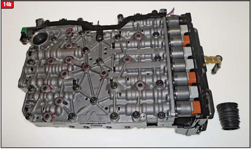
The bottom side of the valve body shows the solenoids, all nine of them (Figure 14b). There are so many solenoids that ZF could not fit all of them at one end of the body. Solenoid #9 is at the other end and has a separate harness. As with other ZF solenoids, 8HP solenoids do not all function the same but are at least color coded. Diagnostic procedures will apply to 8HP models as usual.
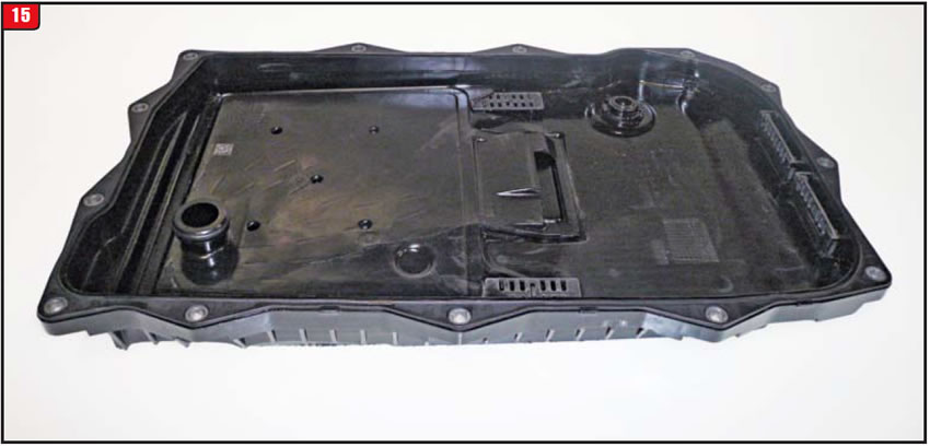
The bottom pan, at least on the 8HP45, is a traditional ZF plastic pan that has the filter molded into it (Figure 15) – not a cheap fluid/filter service. It also has a molded rubber gasket. Other models may have a metal pan. Time will tell.
The 8HP is an engineering feat to squeeze out that many gears within that case. More speeds coming? Stay tuned.


April 2014 Issue
Volume 31, No. 4
- ZF 8HP rear-wheel-drive eight-speed


