Technically Speaking
- Subject: Transmission malfunctions with unexplained causes
- Unit: ZF 5HP24
- Vehicle Application: 2001 Jaguar XJ8
- Essential Reading: Rebuilder, Diagnostician
- Author: Wayne Colonna, ATSG, Transmission Digest Technical Editor
Back in 2003, when Transmission Digest hosted Showpower in Charlotte, N.C., I did a presentation called “Odds with an End,” an array of transmission malfunctions featuring oddities from the “X” files.
To this day I still receive calls from some who attended this seminar saying, “Hey, Wayne, I’ve got another one you can add to your X-file list!”
The idea of labeling transmission malfunctions as fitting into an X-file category is the result of knowing what fixed the problem but having difficulty explaining why.
Terry Coote from Automatic Transmission Works in Fort Worth was kind enough to share with me a problem that really kicked his butt and that I would categorize as belonging to the X-file list.
He had a 2001 Jaguar XJ8 with the ZF 5HP24 transmission that he originally built in March 2011 for a dealership. It returned to his shop over the Thanksgiving holiday eight months later. When it left it was working flawlessly, but when it returned it was operating erratically.
The problem ran him around for two weeks as he was trying to figure it out. It set code P1722 on three occasions during that time and defaulted to failsafe with and without this code set. It had second-gear starts a few times and sudden neutralizing. The only consistent problem was a poor 3-4 shift. Terry described this shift as being a soft, muddy kind of a slip shift, but it was this way only after one drive cycle. You could run through the gears as many times as you would like after that and the 3-4 shift was fine. But once you cycled the ignition, the first drive cycle would repeat that soft, muddy-type 3-4 shift.
They removed the transmission and had many pairs of eyes looking at it trying to find the problem, but nothing was found. Since it was a job from the dealership, the dealer was constantly pressuring Terry to get the car back (nothing like adding more pressure to an already-stressful situation).
Jaguar defines code P1722 as a Transmission Stall Speed Failure and cites these possible source(s):
- Output-speed-sensor signal faulty
- Harness fault
- Connector pin(s) bent, loose or corroded
- Transmission control module failure
- Transmission mechanical fault.
Although this list may reveal the cause of P1722 under “typical” circumstances, it didn’t this time around. Furthermore, what actually caused this problem would have typically caused an intermittent no-start complaint rather than the erratic transmission operation Terry experienced.
If you look at the partial wiring diagram in Figure 1, you will notice that the battery is in the trunk. One of the positive leads of the battery goes to a High Power Protection Module, also in the trunk. This module then supplies power to the two rear heel-board fuse boxes, the engine-management and engine-compartment fuse boxes. It also supplies power to the starter motor and generator after it passes through a stud called the “False Bulkhead Stud Connector.”
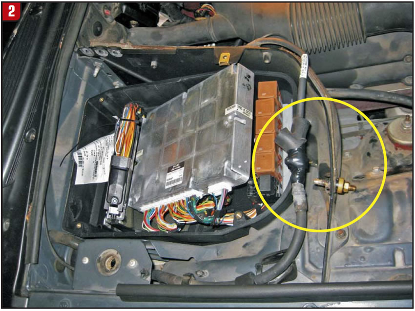
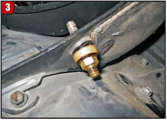
This stud is by the ECM/TCM box in the right-rear corner of the engine compartment (figures 2 and 3). Terry provided the photos showing where he already had removed the wires going to this stud with a temporary bypass connection.
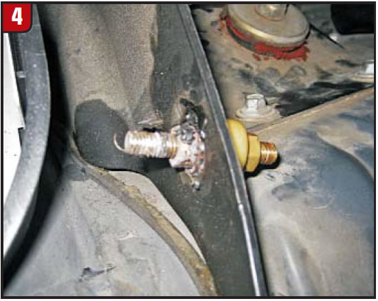
Upon a closer view of one side of this offending stud (Figure 4), there is evidence of the power wire that was attached to it arcing because of a poor connection. Once Terry bypassed this stud all his concerns immediately disappeared.

Apparently this bad connection caused some type of voltage drop in the system that caused the TCM to operate the transmission erratically. This assumption seems valid when you consider how the 3-4 shift had a problem only after one ignition cycle. With a bad connection from the High Power Protection Module to the starter through this stud, enough of a voltage discrepancy occurred during crank to affect TCM operation through the first 3-4-shift drive cycle. But with its continued erratic voltage, the intermittent second-gear starts, neutralizing and failsafe would occur.
There are a few obvious reasons why this compromised connection through the False Bulkhead Stud Connector was so elusive. As first mentioned, this problem usually causes an intermittent no-start complaint that was not occurring in this vehicle. Second, why did the TCM produce code P1722 and not the codes that relate to its ignition supply voltage?
According to Jaguar, the TCM monitors battery and ignition switched supply voltages at terminals 54 and 55. A permanent supply is used to maintain a battery-backed “memory” at terminal 26. Should this supply be cut because of battery disconnection, the “adaptive shift” values will be lost. This will result in a small reduction in shift quality until the adaptations are “re-learned.” Should the ignition switched supply fall outside prescribed limits, the TCM will adopt a “limp home” mode resulting in inconsistent solenoid control.
DTC P1793 will be logged should the TCM adopt “limp home” as a result of the supply voltage being greater than 16V or less than 7V with an engine speed greater than 1,600 rpm. Should the ignition supply be greater than 7V but less than 9V the TCM will hold the gear that it has currently selected. If after 2.5 seconds, with the engine speed greater than 1,600 rpm, the voltage remains at this level, DTC P1789 will be logged and “limp home” mode adopted. The 2.5-second delay is built in to prevent reaction to a momentary voltage fluctuation.
Could it be that the voltage fluctuation did not fall within the parameters required to set these codes yet still caused the TCM to act irrationally? This could be why the stud is called a FALSE Bulkhead Stud Connector and why it makes for a great X-file piece.
Although I cannot give you the exact reason why the TCM acted so irrationally, it still is good for you to know that it can happen and what caused it and not have your butt kicked as it did with Terry.
To add a bit more useful information to this article, should the battery become disconnected, XK8 models will require having the window-position memory reset. But to expedite the adaptive learning process for some functions of the ECM, Jaguar suggests that you perform the following procedure:
Warning: Perform this procedure with the vehicle on a firm surface (not on a lift) after ensuring that no danger exists to surrounding personnel or property. Caution: Do not exceed the engine speeds and time durations listed.
- Engage P and allow the engine to reach normal operating temperature.
- Press the A/C button to turn the climate control off.
- Apply the service and parking brakes, and move the transmission selector lever to D.
- Allow the engine to idle for an additional two minutes.
- Gradually raise the engine speed to 950 rpm. Hold this speed for 45 seconds.
- Raise the engine speed to 1,200 rpm. Hold this speed for 45 seconds.
- Raise the engine speed to 1,500 rpm. Hold this speed for 30 seconds.
- Allow the engine to return to idle. Move the selector lever to P and switch off the engine.
Comprehensive Component Monitor Transmission Drive Cycle
The Comprehensive Component Monitor transmission drive cycle will check all transmission-system components:
- Engine and transmission at normal operating temperature. Ignition off; ensure that SPORT mode is NOT selected.
- With gear selector in P and the ignition on, check gearshift interlock by trying to move selector without pressing the brake pedal. Verify P state illumination.
- Press and hold the brake pedal. Move the gear selector to R. Verify R state illumination.
- Set the parking brake. Press and hold the brake pedal. Attempt to start the engine. The engine should not start.
- Move the gear selector to N. Verify N state illumination. Start the engine.
- With the hand brake set and the brake pedal pressed, move the gear selector to the remaining positions in the J-gate (D, 4, 3, 2) for five seconds each. Verify the state illumination in each position.
- Move the gear selector back to 4. Verify 4 state illumination.
- Move the gear selector to D. Verify D state illumination.
- Move the gear selector to N. Verify N state illumination.
- Select R, release the brakes and drive the vehicle in Reverse for a short distance.
- Stop the vehicle.
- Select 2 and drive the vehicle up to 65 km/h (40 mph). Hold 65 km/h (40 mph) for a minimum of five seconds.
- Select 3 and hold 65 km/h (40 mph) for a minimum of five seconds.
- Select 4 and hold 65 km/h (40 mph) for a minimum of five seconds.
- Select D and accelerate to a minimum speed of 80 km/h (50 mph). Hold 80-129 km/h (50-80 mph) for a minimum of 1.7 kilometers (1 mile).
- Stop the vehicle; do not switch off the engine.
- Use WDS Datalogger (or capable scan tool) to check total number of DTCs set to ensure that transmission DTC monitoring is complete.


