Technically Speaking
- Subject: Redesign of transaxle to add fifth gear
- Unit: Ford FNR5/Mazda 5NR5
- Vehicle Applications: 2006-up Ford Fusion, Mercury Milan, Lincoln MKZ & Zephyr, Mazda 3, Mazda 6
- Essential Reading: Rebuilder, Diagnostician
- Author: Wayne Colonna, ATSG, Transmission Digest Technical Editor
Ford FNR5/Mazda 5NR5
Last month’s article was about the clever engineering redesign of the 41TE with the addition of a pressure-control solenoid to reduce line pressure under various conditions. The primary reason for this change was to increase fuel economy, and now this redesigned transmission is called the 41TES.
This month I’m revealing another very clever engineering redesign with a Ford/Mazda transmission. The Ford FNR5 is the five-speed version of the previous four-speed 4F27E. Mazda uses the 5NR5 designation for its redesigned FN4A-EL.
This transmission is currently being used behind four-cylinder engines in the following 2006-and-later vehicles:
- Ford Fusion
- Mercury Milan
- Lincoln MKZ & Zephyr
- Mazda 3 & 6
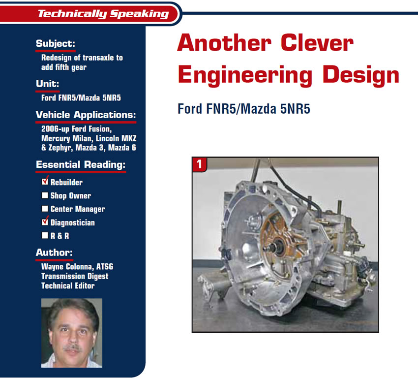
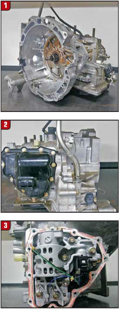
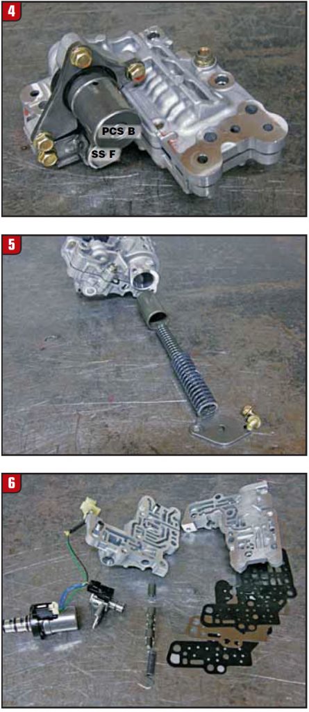
At first glance this transmission looks like the 4F27E (see Figure 1), but spin the transmission around and you will find a side pan (see Figure 2). Behind this second pan is none other than a secondary valve body (see Figure 3).
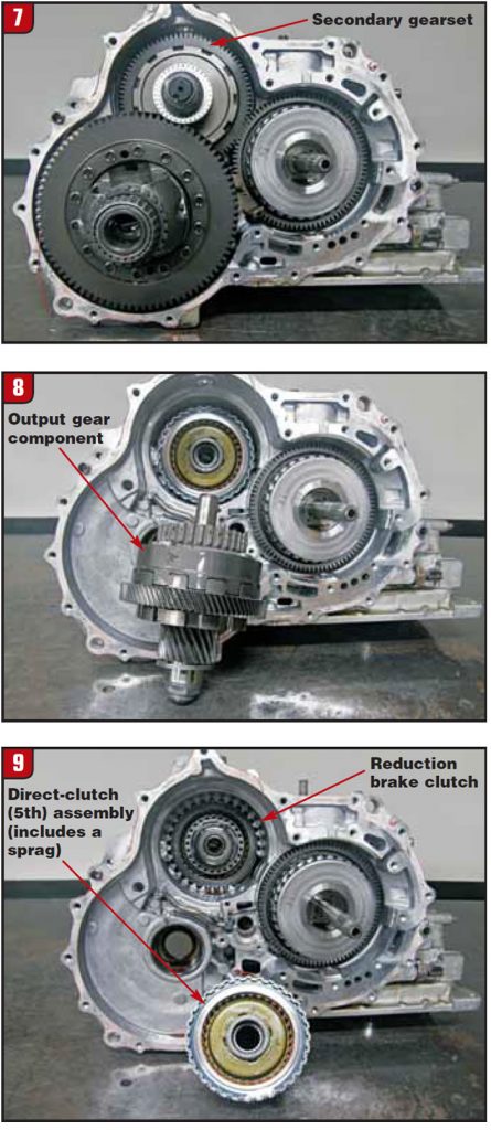
This valve body contains shift solenoid F, pressure-control solenoid B, an accumulator piston and one shift valve (see figures 4, 5 and 6).
This valve-body assembly operates a secondary gearset inside the transmission as shown in Figure 7. This secondary gearset consists of an output planetary-gear component (see Figure 8), a direct-clutch (5th gear)/sprag assembly and a reduction brake clutch (see Figure 9).
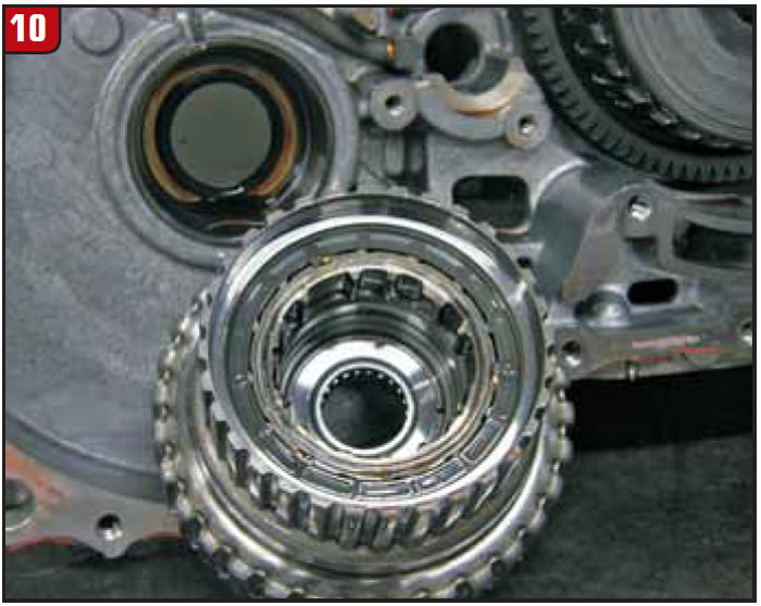
In a nutshell, the reduction brake clutch is applied in 1st, 2nd, 3rd, 4th and reverse. It releases in 5th when the direct clutch applies. The sprag in the back side of the direct-clutch-drum assembly (see Figure 10) assists in the 4-5 and 5-4 shifts as these clutches apply and release.
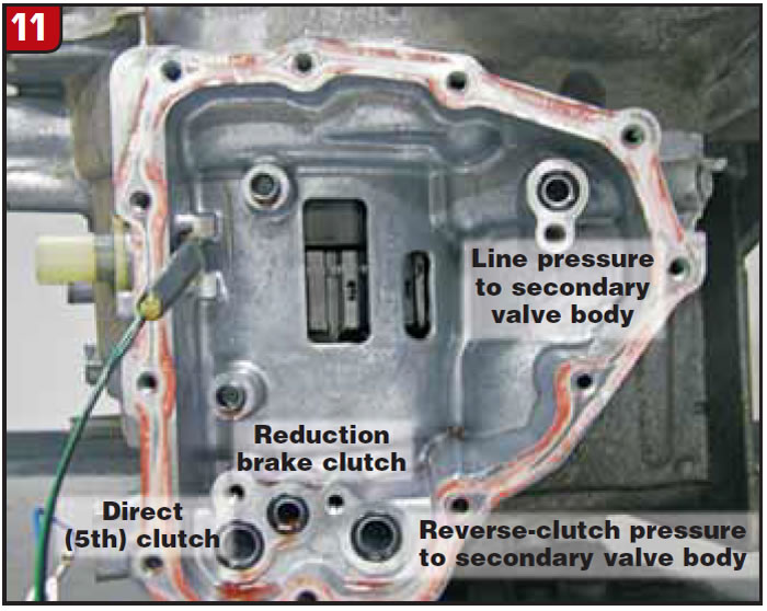
Since very little information is available for this transmission I needed to do some circuit tracing to determine how the secondary valve-body assembly controls the secondary gearset. I started with the main case and worked my way into the secondary valve body, where I was then able to identify the secondary valve-body case passages, as you can see in Figure 11.
From this information I was able to understand the operation of the secondary valve-body assembly enough to draw out the hydraulics to show you the simplicity and cleverness of the engineers’ design for a fifth-gear operation in an existing four-speed 4F27E.
As you study figures 12, 13 and 14 you will see that shift solenoid F operates the one shift valve and pressure-control solenoid B controls clutch pressure. I had to take some liberty here, as I didn’t know what Ford or Mazda calls this shift valve, so I have called it the reduction/5th-clutch shift valve.
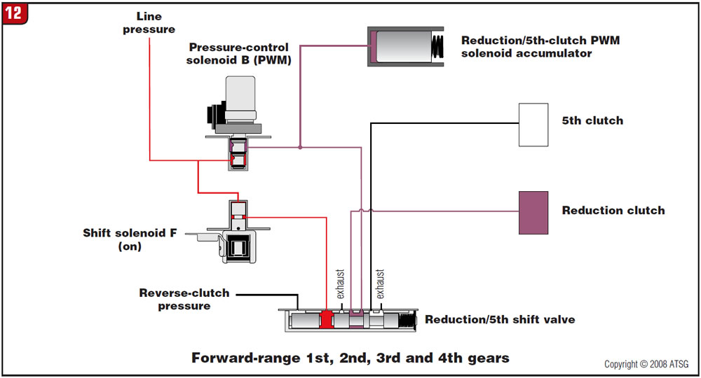
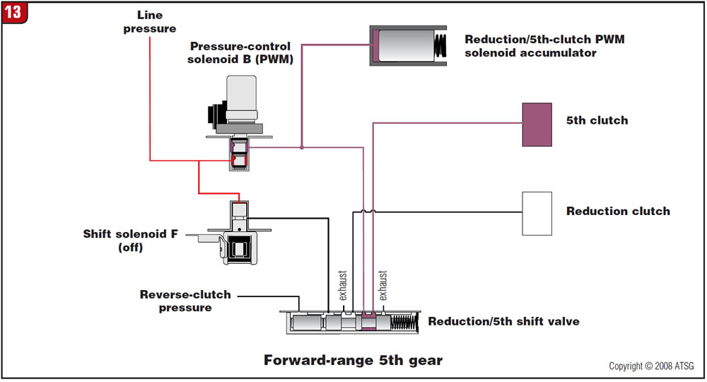
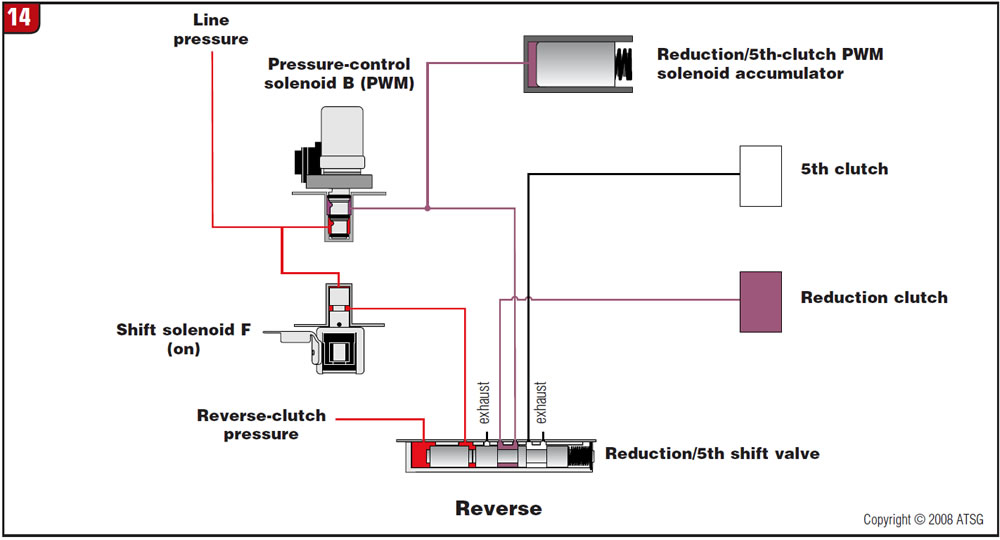
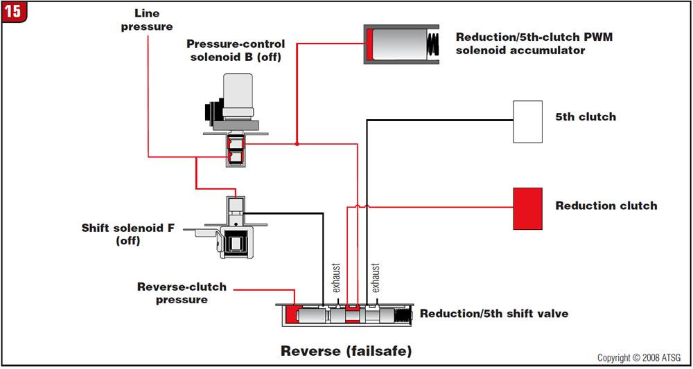
In short, when the reduction/5th-clutch shift valve is held closed by spring tension, the valve is in the 5th-clutch apply position. When the valve is stroked by shift solenoid F, the valve is in the reduction-clutch apply position. PCS B controls the application of both clutches, and a sprag assists in the 4-5 and 5-4 timing. The accumulator is used to absorb the pulsing from PCS B. Reverse-clutch oil is used to stroke the reduction/5th-clutch shift valve to ensure that the valve is in the reduction-clutch apply position, for without this clutch there would be a loss of reverse. This also allows for a reverse engagement in failsafe conditions even with shift solenoid F being off (see Figure 15).
Now, you may be thinking that if both shift solenoid F and pressure-control solenoid B turn off in the Drive range, that would cause the 5th clutch to turn on as Figure 16 shows, and you are right.
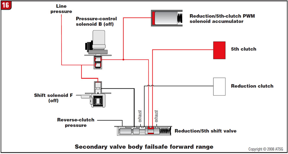
All that the secondary planetary gearset does is provide a speed reduction in the first four gears through the reduction clutch. When the reduction clutch releases and the direct (5th) clutch applies, the secondary planetary gearset locks into a 1:1 ratio, eliminating the speed reduction and allowing a higher-speed overdrive ratio to be obtained after 4th.
According to what little information is available, the computer will default to 3rd gear in the main gearbox of the transmission should it need to enter a failsafe mode. If the solenoids on the secondary valve body also shut down, this will apply the direct (5th) clutch, making a slightly higher-speed third-gear ratio failsafe.
Another clever engineering design.
Many thanks to the good folks at Alto for providing ATSG with an FNR5 transmission.


