A Different Fix for an Old Problem - Transmission Digest

A Different Fix for an Old Problem

The problem of bore wear on torque-converter-clutch pistons has been around since lockup torque converters were born. The rotational restriction on the pistons is handled by splines, pins or fingers. But centering the pistons is generally the sole responsibility of the bore. Any out-of-balance movement of the piston will cause the piston bore to scuff against the turbine hub when it moves to apply or release the clutch. Indexing the piston to the turbine and balancing this unit helps minimize bore wear. (See the article on indexing TCC-piston damper assemblies to turbines, Transmission Digest, March 2006.)

A Different Fix for an Old Problem

Torque Converter Tech Tips

Author: Ed Lee

Torque Converter Tech Tips

  • Author: Ed Lee

The problem of bore wear on torque-converter-clutch pistons has been around since lockup torque converters were born. The rotational restriction on the pistons is handled by splines, pins or fingers. But centering the pistons is generally the sole responsibility of the bore. Any out-of-balance movement of the piston will cause the piston bore to scuff against the turbine hub when it moves to apply or release the clutch. Indexing the piston to the turbine and balancing this unit helps minimize bore wear. (See the article on indexing TCC-piston damper assemblies to turbines, Transmission Digest, March 2006.)

But having a perfectly balanced assembly and expecting it to remain that way throughout its lifespan is not realistic. Torque-converter rebuilders will always have to deal with piston-bore wear.

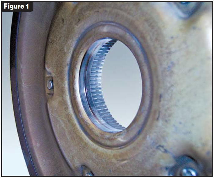
The area of the piston bore that is the sealing surface seldom shows any wear because it is not used for centering. Of course, the rest of the bore will wear faster because of the small surface area remaining.

The E4OD piston in Figure 1 is a good example of bore wear. Machining the piston and installing a replacement sleeve is the current industry fix. This method works well, and most replacement sleeves are harder than the original bore, for longer life.

Dick Lewis of Midwest Converter Supply decided to address his bore problems at a different level. Dick’s shop renews the bore surface by spray-welding the original bore and then remachines the bore to its original dimension (see Figure 2).

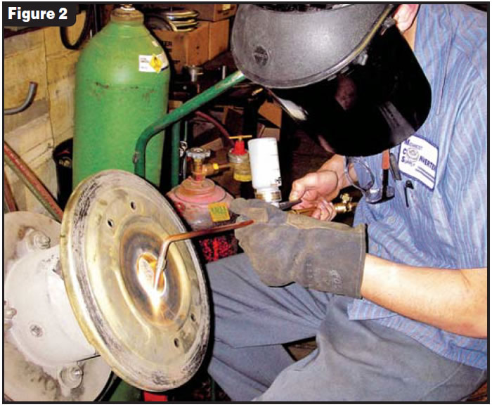
The piston is placed onto a standard welding turntable. A sleeve attached to the turntable centers the piston and also keeps any welding debris from getting into the damper assembly. The turntable is set at a 45° angle, and the piston’s own weight keeps it in position.

The torch operator shown in Figure 2 is using a “Stoody” jet-spray torch (model No. JS-100, made by Thermadyne Corp.). The media used for welding is held in the canister mounted on the torch. The type of welding media used controls the hardness of the finished weld. For this application media No. HSW25 was used, giving a finished hardness of 36 to 38 Rockwell – hard enough to extend the life expectancy of the part and still soft enough for machining to a good surface finish. The amount of the weld being applied is controlled by the lever on the torch below the welder’s right thumb.

There are many different gas combinations that will work with this torch, but the oxygen/acetylene combination being used in this instance seems to work best. The welding process takes about four to five minutes from start to finish.

Normally, bad bores are found during the cleanup process and repaired before bonding. But if you don’t discover a bad bore until after the piston is bonded, you can still make your bore repairs on the bonded piston.

Ed Lee is a Sonnax technical specialist who focuses on issues of interest to torque-converter builders. ©Sonnax 2006

You May Also Like

Sherlock Holmes Approach to an AB60 No-Move Situation

The effectiveness in diagnosing automatic transmission malfunctions is an art form. Although there are similarities among the wide varieties of transmissions on the road, each transmission has its own peculiarities. Aside from having mechanical, hydraulic, and electrical hardware systems to contend with, software/programming issues and various vehicle platforms make diagnostics much more difficult.  Using scopes provides

ab60

The effectiveness in diagnosing automatic transmission malfunctions is an art form. Although there are similarities among the wide varieties of transmissions on the road, each transmission has its own peculiarities. Aside from having mechanical, hydraulic, and electrical hardware systems to contend with, software/programming issues and various vehicle platforms make diagnostics much more difficult. 

GM 6T40 Pump Identification Guide

The 6T40 was introduced in 2008 for General Motors front-wheel-drive cars in the Chevrolet Malibu and has gone through several changes throughout its three generations, specifically in the pump area. The 6T40 is closely related to the more lightweight 6T30 and the heavier duty 6T45 and 6T50. Generation one started phasing out during the 2012

Seeing the Forest AND the Trees

They say that the proverbial phrase “I couldn’t see the forest for the trees” means that a person or organization cannot see the big picture because it focuses too much on the details. Related Articles – 4L60E Harsh 1-2 Shift – TASC Force Tips: Diagnosing 8L45 & 8L90 Shift Complaints – TASC Force Tips: Hydraulics

The Manifold Pipeway

The Honda six-speed transmission has been on the bench of many specialty shops for one reason or another (figure 1). But, for those of you who have yet to lay your hands on one, mounted on the upper side of the unit is one of the largest, if not the largest solenoid and pressure switch

8L90 Vacuum Testing

Below are the diagrams for vacuum testing GM 8L90 transmissions. Note: OE valves are shown in rest position and should be tested in rest position unless otherwise indicated. Test locations are pointed to with an arrow. Springs are not shown for visual clarity. A low vacuum reading indicates wear. For specific vacuum test information, refer

Other Posts

Critical Wear Areas & Vacuum Test Locations for FORD 6R80/6R100

Note: OE valves are shown in rest position and should be tested in rest position unless otherwise indicated. Test locations are noted with an arrow. Springs are not shown for visual clarity. Low vacuum reading indicates wear. For specific vacuum test information, visit www.sonnax.com. Related Articles – Hydraulics Fundamentals: Shift & Relay Valves – Another

Hydraulics Fundamentals: Shift & Relay Valves

Shift valves and relay valves share a lot of the same duties. This article is one of a series by Sonnax exploring how valves and hydraulic circuits work and what results when they quit functioning correctly.

Another 62TE ‘No-Move’ Possibility

Most seasoned techs have several quick diagnostic steps they take when faced with a transmission malfunction. The type of problem and transmission determines which steps to take. For example, a “no-move” condition. Related Articles – Ford 8F35 maintenance tips: Planetary failure and no-pressure conditions – Don’t fear customer complaints about CVTs – Shift Pointers: A Chrysler

Hydraulics Fundamentals: Clutch Regulator Valves

Knowing how these circuits work and the slightly different variations that the manufacturers utilize should pinpoint any valve body-related issues