A Balancing Act - Transmission Digest

A Balancing Act

There is very little information written about this transmission concerning the valve body and its associated hydraulic operations. For this reason ATSG has produced a Technician Guide that provides extensive information including valve-body mapping and a complete set of hydraulics. In the process of developing this guide, we discovered a unique way in which this unit controls clutch application. The high-clutch amplifier valve in the upper valve body (Figure 2) serves as a perfect example.

A Balancing Act

Technically Speaking

Subject: Operation of high-clutch amplifier valve
Unit: RC4A-EL/JR405E
Essential Reading: Rebuilder, Diagnostician
Author: Wayne Colonna, ATSG, Transmission Digest Technical Editor

Technically Speaking

  • Subject: Operation of high-clutch amplifier valve
  • Unit: RC4A-EL/JR405E
  • Essential Reading: Rebuilder, Diagnostician
  • Author: Wayne Colonna, ATSG, Transmission Digest Technical Editor

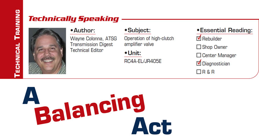
Here in the United States there is a four-speed, computer-controlled automatic transmission called the RC4A-EL or the JR405E (Figure 1), used in Mazda’s RX8 vehicle from 2003 to 2006. According to year-end sales reports provided by Automotive News, about 60,000 of these cars were sold and are on the road today. So chances are one may show up in your shop for repairs.

There is very little information written about this transmission concerning the valve body and its associated hydraulic operations. For this reason ATSG has produced a Technician Guide that provides extensive information including valve-body mapping and a complete set of hydraulics. In the process of developing this guide, we discovered a unique way in which this unit controls clutch application. The high-clutch amplifier valve in the upper valve body (Figure 2) serves as a perfect example.

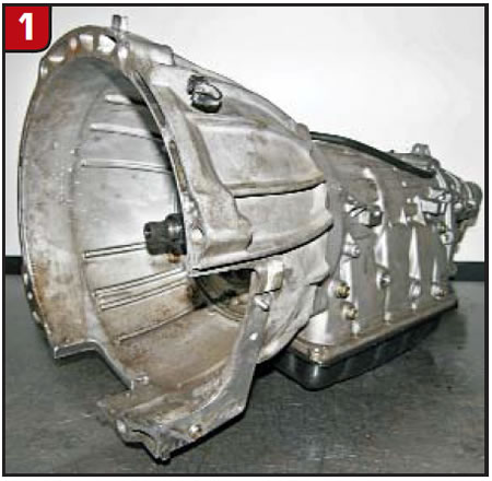
This valve is fed with line pressure directly from the manual valve (Figure 3) as soon as the Drive range is selected.

This is when and where one of the balancing acts that occur in the valve body begins. The high clutch is off in 1st and 2nd gears and is applied in 3rd and 4th. Shift solenoid C is used to stroke this high-clutch amplifier valve. This is a duty-cycle-type solenoid (50Hz) that is normally applied, meaning that when the duty cycle is high the clutch is off and when the duty cycle is low the clutch is on.

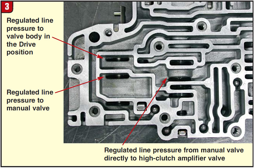
Putting these parameters together, Figure 4 is a partial hydraulic schematic of what this looks like in Drive 1st and 2nd gears.

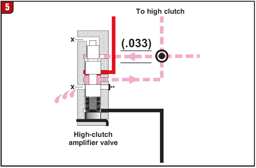
Regulated line pressure from the manual valve goes directly to the high clutch amplifier valve, where it then is directed to the high-clutch apply passage. But it is also routed to the back end of the valve through a 0.033-inch orifice. This closes the line-pressure feed to the valve while opening the apply path to an exhaust. The spring on the valve weighs only a couple of ounces but apparently has enough tension to close the valve, which again opens the line-pressure feed to the apply path and the cycle repeats itself (Figure 5).

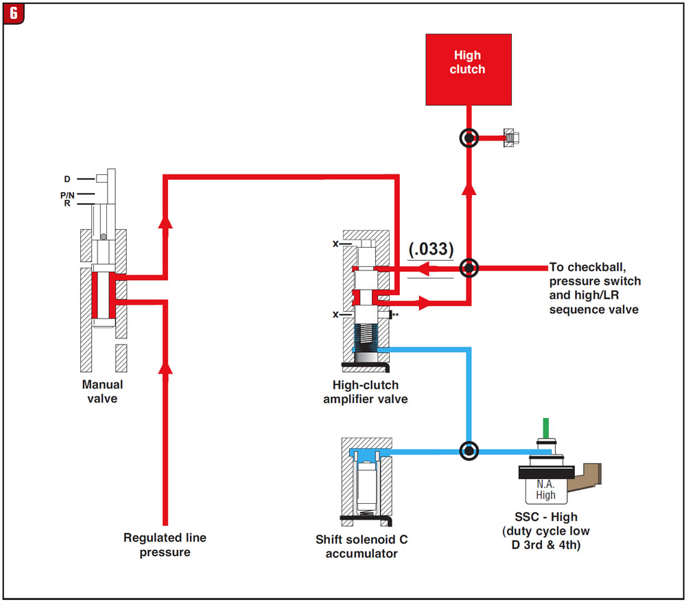
This balancing act between feed and exhaust seems to provide pre-fill clutch pressure so that when the circuit is actually charged (Figure 6), the clutch applies sooner since it does not have to fill a dry apply passage.

Several obvious conditions must be met for this balancing act to work properly; otherwise, the high clutch could apply prematurely. The clutch circuit is monitored by a pressure switch rated at 50-70 psi, which is high enough to allow lesser pressure to be present without notifying the computer. For example, 10 to 15 psi is well below the pressure-switch rating but could easily drag the clutch in 1st and 2nd, taking it out in a relatively short time.

So if one of these units finds its way into your shop with high-clutch failure, be sure to check the integrity of this valve lineup (bore plug, valve bore etc.) and the mechanical operation of the solenoid and pressure switch. There is a low-clutch and 2-4-clutch amplifier valve that functions in this same manner, so if either of these clutch assemblies has failed, you would need to make the same inspection of their respective circuits.

Many thanks to Seth and the good folks at AACTION Transmissions in Miami for the use of this transmission.

You May Also Like

Sherlock Holmes Approach to an AB60 No-Move Situation

The effectiveness in diagnosing automatic transmission malfunctions is an art form. Although there are similarities among the wide varieties of transmissions on the road, each transmission has its own peculiarities. Aside from having mechanical, hydraulic, and electrical hardware systems to contend with, software/programming issues and various vehicle platforms make diagnostics much more difficult.  Using scopes provides

ab60

The effectiveness in diagnosing automatic transmission malfunctions is an art form. Although there are similarities among the wide varieties of transmissions on the road, each transmission has its own peculiarities. Aside from having mechanical, hydraulic, and electrical hardware systems to contend with, software/programming issues and various vehicle platforms make diagnostics much more difficult. 

GM 6T40 Pump Identification Guide

The 6T40 was introduced in 2008 for General Motors front-wheel-drive cars in the Chevrolet Malibu and has gone through several changes throughout its three generations, specifically in the pump area. The 6T40 is closely related to the more lightweight 6T30 and the heavier duty 6T45 and 6T50. Generation one started phasing out during the 2012

Seeing the Forest AND the Trees

They say that the proverbial phrase “I couldn’t see the forest for the trees” means that a person or organization cannot see the big picture because it focuses too much on the details. Related Articles – 4L60E Harsh 1-2 Shift – TASC Force Tips: Diagnosing 8L45 & 8L90 Shift Complaints – TASC Force Tips: Hydraulics

The Manifold Pipeway

The Honda six-speed transmission has been on the bench of many specialty shops for one reason or another (figure 1). But, for those of you who have yet to lay your hands on one, mounted on the upper side of the unit is one of the largest, if not the largest solenoid and pressure switch

8L90 Vacuum Testing

Below are the diagrams for vacuum testing GM 8L90 transmissions. Note: OE valves are shown in rest position and should be tested in rest position unless otherwise indicated. Test locations are pointed to with an arrow. Springs are not shown for visual clarity. A low vacuum reading indicates wear. For specific vacuum test information, refer

Other Posts

Sometimes, a diagnostic code is all you need

With ATSG having the opportunity to help shops solve problems, sometimes we get faced with some real doozies. A shop will call and give us a laundry list of DTCs, leaving us to think someone must have a bulkhead connector unplugged. We then go through the arduous task of deciding which codes prompted other codes

10L80 and 10R80 pump gear differences

You may have seen an article in the August 2023 issue of Transmission Digest called “GM 10L80: A new kind of pump noise,” which goes over how the front cover housing in the 10L80 is fitted with a converter drive gear and idler gear. The idler gear drives the pump’s driven gear, and is press

Spotting different 68RFE designs through the years to avoid issues

The Chrysler 68RFE has had several changes through the years. Its four-speed predecessor began with a noisy solenoid pack identified by a black colored pass-through case connector (seen in Figure 1).  Related Articles – A guide to common GM, Ford and Nissan programming issues – Shift of the shaft: Diagnosing Chrysler 48RE manual shaft issues

Sometimes, you should sweat the small stuff

It’s a common phrase: There may have been a time when you worried about something, and someone who knew what you are going through said, “Hey, don’t sweat the small stuff.” Sometimes, this may be good advice. But other times, it may be wise to handle the small stuff before it becomes bigger “stuff.”  Related