Torque Converter Tech Tips
- Author: Ed Lee
740/1740 codes tell you there is excessive slip at the TCC clutch. The engine and transmission output speeds are constantly being monitored. You can compare the difference in the two speed rates to determine transmission slip. If the RPM parameters for a slip in a given gear are met and TCC apply has not been commanded, you will see a gear-ratio code. But, if the RPM parameters for a slip in a given gear are met and TCC apply has been commanded, you will see a (TCC slip) 740 code.
Sometimes the reason for the 740 code is not found within the transmission or torque converter. A restricted cooler or line is a good example. Using a fluid without the correct frictional qualities (the wrong fluid) may cause a 740 code. The hydraulic integrity of the valve body (worn bores) and the pump (excessive clearance or cross leaks) are two possible culprits that also must be eliminated. If all of these possibilities check out OK, it’s time to take a closer look at the torque converter.
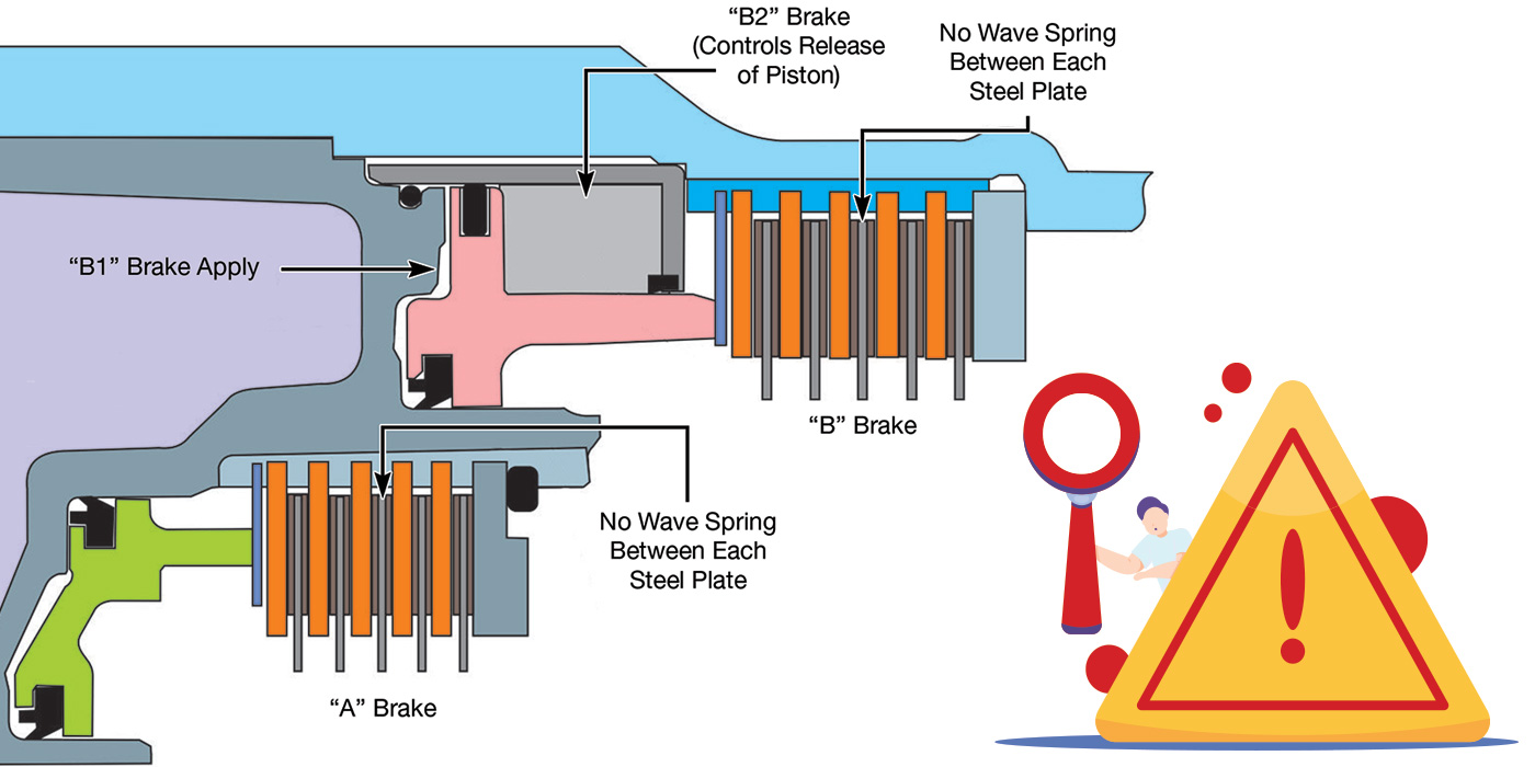
Converter charge oil enters the converter through the input (turbine) shaft. When this oil exits the end of the input shaft, its path around the splines (between the shaft and turbine hub) is blocked by a seal. The only remaining path is through the grooves on the outside of the turbine-hub bushing. The oil then passes between the turbine hub and cover, fills the area in front of the lockup piston and eventually spills around its outside edge, where it continues to fill the rest of the converter before exiting as lube oil.
The action of the converter charge oil between the piston and cover is what keeps the piston from dragging on the cover when the converter is in the TCC-release mode. When the switch valve is stroked to the TCC-apply position, the converter charge oil switches and goes straight to the cooler. The residual pressure between the piston and the cover (release oil) then is vented off through the slot in the plate but first goes past the switch-valve spool. This allows the oil between the lockup piston and cover to exit the converter through the input shaft so that the piston can move forward, contacting the cover for lockup apply. Any restriction to converter charge oil will affect converter fill, which is also converter-clutch release oil. A restriction also will prevent converter release oil from exhausting for lockup apply to occur. Unfortunately, there are many ways for a restricted passage to occur.
Chrysler Rear-Wheel-Drive Overdrive Transmissions
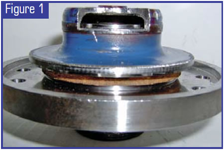
When the input (turbine) shaft is in its proper position in relation to the inside of the pilot (cover), it will look like the cutaway in Figure 1. The input shaft is about 0.125 inch from the cover when the converter is installed to its proper depth. The proper way to check clearance between the converter and flex plate is to push the converter back until the hub bottoms in the pump, then measure the distance between the flex plate and the converter pad.
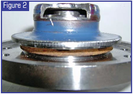
This measurement needs to be a minimum of 0.125 inch but no more than 0.250 inch. The minimum of 0.125 inch is important to allow for a certain amount of converter expansion (ballooning), and to allow for a certain amount of movement by the flex plate. If the flex plate is bent, it could allow the converter to move rearward and restrict the flow of oil between the input shaft and cover. The example shown in Figure 2 was close enough to cause a 740 code.
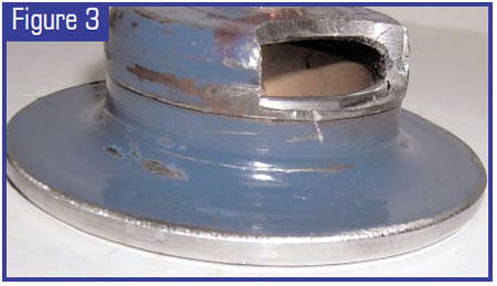
The turbine-hub bushing is the next element that may cause a restriction. When the bushing is installed properly, the top of the bushing is flush to 0.020 inch up from the top of its bore. The bore for the bushing is in the pilot area of the cover, and the top of the bushing bore is recessed about 0.028 inch below the thrust area for the turbine hub. The cutaway in Figure 3 shows a bushing that was installed 0.080 inch (twice the thickness of a dime) below flush. You are viewing the bushing from the bottom side, so you can see that flow was completely restricted. This, too, caused a 740 code.
The next elements that may cause a flow restriction are the thrust washers or bearing that handle the axial thrust forces between the turbine hub and cover. Since all the oil that enters or exits the converter through the input shaft must pass through this area, the torque-converter rebuilder must be aware of the differences. Hold the turbine hub in your hand with the cover side facing up. Now, place whatever you are using between your thrust surfaces onto the hub (for example, a thrust washer or bearing), and, last, put a turbine-hub bushing onto the turbine hub.
Imagine the oil flowing through the grooves on the outside of the bushing toward the thrust washer or bearing. The tolerance between the inside diameter of the washer or bearing and the outside diameter of the turbine hub usually is close enough to prevent much flow between them. The cover does not have any passages for oil flow that extend beyond the grooves on the outside of the bushing. If you use a solid washer in this application (brass, fiber or phenolic), the only flow that you will have is the oil that squeezes past the internal clearances that you have built into your converter. This also will usually set a 740 code.
If your thrust washer has grooves on only one side, you also need to pay attention to this. When you place the thrust washer on your turbine hub with the grooves facing up (toward the cover) you can see that there are passages for oil flow, but if you can place the thrust washer on the turbine hub with the flat side up, you will see that when the oil exits the grooves on the outside of the turbine-hub bushing, it has no place to go. This also may cause a 740 code. Some bearings are well equipped for oil flow (the 604, for example). Other bearings may restrict the flow of oil. Place your bearing on your turbine hub and make sure that it will not restrict flow.
Chrysler Front-Wheel-Drive Transmissions
The 518 and 604 converters are first cousins, hydraulically speaking. They share many of the same flow characteristics and several of the same problems.
The input shaft of the 604 has more clearance at the cover, but clearance probably would not be an issue anyway, because of the stronger flex plate. The turbine-hub bushing on the 604 looks like a smaller version of the 518 bushing with one less groove on the outside. When the bushing is installed to its proper depth, it is flush to 0.020 inch up from the thrust surface of the cover. This is well above the 0.012-inch flow-relief step at the top of the bore. The machined angle at the bottom of the bore for clearance is greater than its sister angle on the 518 converter and is more flow-friendly.
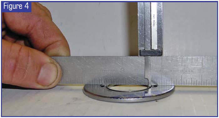
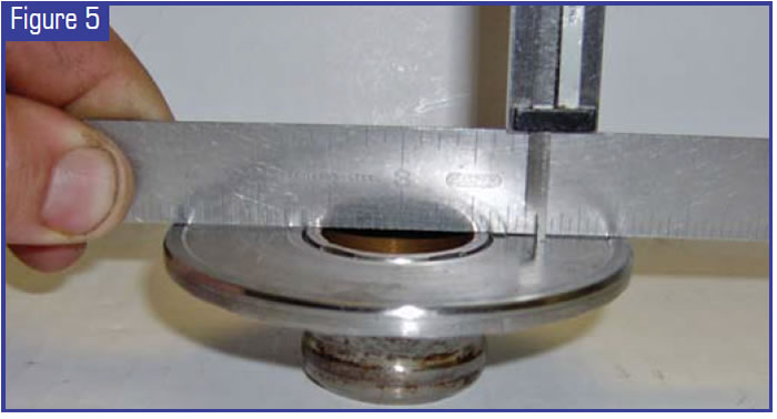
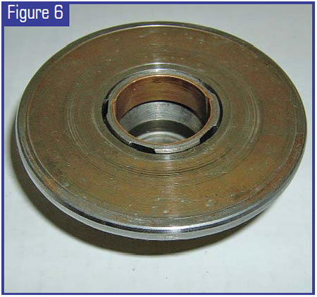
Special attention should be paid to the position of the bushing. Since the inner race of the OE bearing is only 0.015 inch below the thrust surface of the outer race (see Figure 4), it may contact the bushing if the bushing is up 0.020 inch above flush as shown in Figure 5. The 0.005 inch of wear shown in Figure 6 is the result of that contact. This is a bad thing for two reasons: First, the material from the bushing that was worn away by the bearing race has to pass through the bearing, and second, the pinpoint contact of the inner race of the bearing to the bushing may cause the race to flex and eventually fail. Either of these two concerns may help to explain the failure rate of the bearing.
As in the 518 converter, a solid thrust washer may cause flow restrictions and 740/1740 codes. The position of the bushing is also important when you’re using a grooved thrust washer, but not for the same reasons that were important with the bearing. The bushing may keep the thrust washer from contacting the thrust surface of the cover. The distance that the thrust washer is held above the cover translates into extra and unwanted internal clearances, including clutch-release clearance. Since the damper springs have no permanent retaining device, as the clearance between the TCC piston and turbine increases the chances of a spring walking out of place also increase. A small amount of extra clutch-release clearance will allow the spring to walk up the turbine only enough to push the clutch forward, making it drag on the cover. A larger amount of clearance will allow the spring to come completely out of the piston’s spring retainer, causing catastrophic results.
Checking Chrysler’s clutch-release clearance is time-consuming at best, and some rebuilders are relying on the “use thicker friction material and hope” method. Making sure that the turbine-hub bushing is not creating extra clearance may help to eliminate some problems.

Ed Lee is a technical specialist for Sonnax Industries Inc.