TASC Force Tips
- Author: Bob Warnke
A good subtitle for this article could be “pain in the bottom line.” You may have heard the phrase “no pain, no gain,” which is often true in physical conditioning or education but which we prefer not to relate to transmission rebuilding. In this field, the pain – and education – comes in the form of a comeback. It hurts the bottom line to rework or repeatedly give up expensive parts. We are referring to both the cooler line and the profit line.
In this lesson we will hear of a 4R100 in a 2000 7.3-liter diesel with repeated (four times) converter failures.
This is an experience that once learned is never forgotten. During final test drive you notice that the TCC apply seems longer and softer than normal in a 4R100. If you deliver the vehicle it may return because of overheated fluid or converter code 1728 or 1744. Avoiding further diagnosis and swapping converters or coolers can increase the anxiety, as the vehicle returns to the shop after another week. This starts to get your attention. HD converters, new fluid and labor have dissolved the initial profit, so now it’s time to figure out what’s causing this.
What is the problem?
There is not enough pressure at the TCC piston to reduce the slip as the engine input torque increases. Any circuit restriction is more critical on a modulated TCC in the 4R100 vs. the on-off E4OD, because of the size and position of the TCC-control-valve orifices.
To explain the problem we could compare the converter with a hydraulic jack. The cylinder will move only as fast as the fluid fills or is allowed to exhaust. With a jack, the handle or bleed screw is the control.
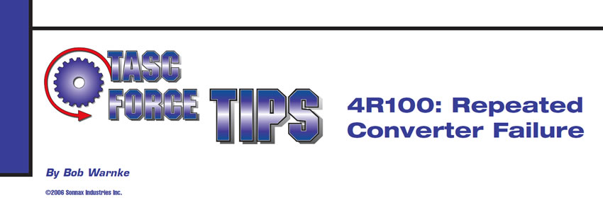
In the 4R100 converter example, the piston travel is controlled by the exhaust of fluid past the turbine hub. If too close/restrictive, the release oil will exhaust slowly as the TCC piston forces the oil out (see Figure 1). There can be other issues affecting the apply and release of the TCC piston. In descending probability, they would include the bypass checkball leaking or stuck open (which is external to the transmission), poor pump volume or modified pump orifices.
Why does this occur on the 4R100?
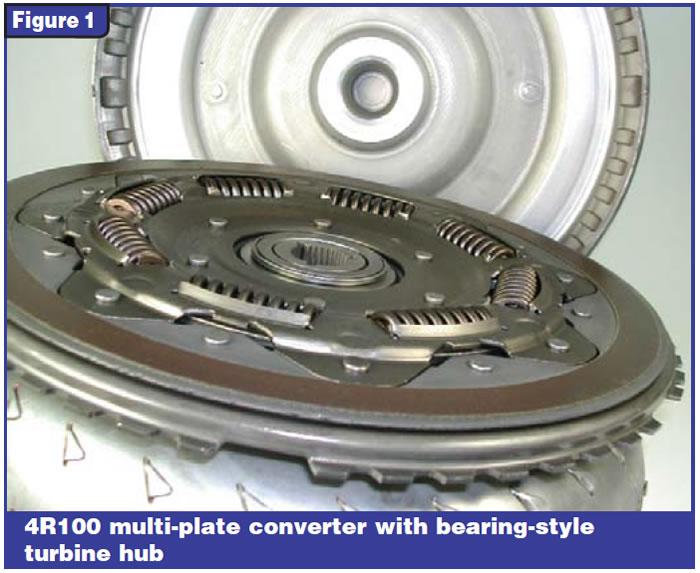
On the modulated converter circuit of the 4R100, the fluid coming from the TCC regulator valve goes unrestricted to the converter-apply piston (see Figure 2). As the TCC solenoid modulates the control valve, the release oil between the piston and the cover exhausts without an orifice. The apply oil now gets priority toward the piston and is restricted toward the cooler direction.
To illustrate the theory, we could use a river’s spillway gate, controlling the water to take an easier path toward a generating turbine. Another example could be the garden water hose. You can see a head-pressure spike from a leakage point as you step on the hose.
In the 4R100 converter the piston gets priority pressure because of the orifice and the cooler receives less pressure and flow. If the orifice size is increased, the TCC piston gets less pressure, but the cooler receives more flow. In this instance, less pressure to an overtaxed TCC piston is not a good practice. Likewise, making the orifice smaller increases pressure at the TCC piston but reduces flow to the transmission lube circuit. The E4OD, by comparison, has an exhaust orifice and apply orifice with its on-off control of the torque-converter clutch.
The 4R100 pump and converter are the easiest of the issues to diagnose for cause and effect.
Now we add the external pressure-bypass circuit. This ball, seat and spring are designed to open at about 60 psi of cooler head pressure, to ensure lube flow around a restricted cooler. Charts, text and graphs aside, think of the radiator and bypass as another person standing farther down the garden hose.
How to isolate the problem:
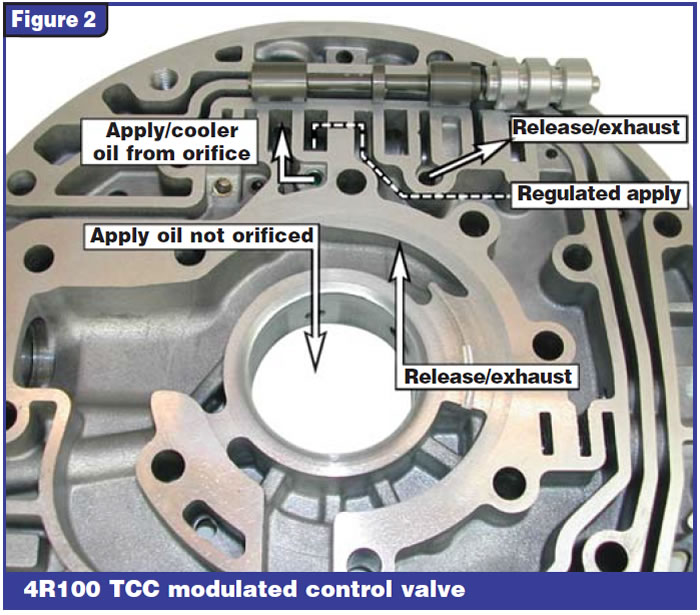
Checking cooler flow and head pressure at the same time is the best method to determine whether there is a problem. If you cannot monitor flow, at a minimum check head pressure (see Figure 3).
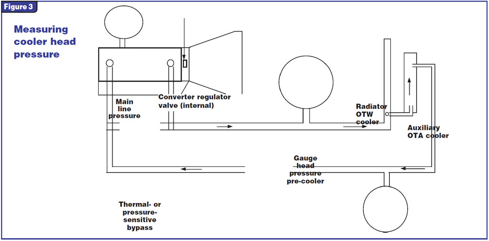
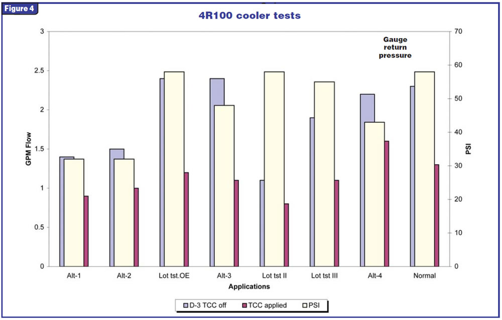
On the 4R100 cooler test graph (see Figure 4), note the two units Alt1 and Alt2. Both had restricted converters. There is minimal difference in flow (see gpm flow rate at far left) during lockup, and head pressure (see psi flow at far right) does not rise to normal. Normal specifications are the last example shown. The Lot test OE example is from pre-repair, with an unrelated problem. The Alt4 test is using the converter from Alt1 and improving the oil flow, then installing it into the same truck. Alt3 is a used OE converter installed into the same Alt1 truck. The other bar graphs are testing various stages with bypass closed or open to isolate it.
Can we apply this information to the E4OD?
Even though the converters may be similar or the same, the hydraulic control is different. The orifices that control the flow to cooler vs. the converter apply differ between the two units. You can verify this by comparing cooler flow on both types of units.
The E4OD will have less cooler flow when TCC is not applied; flow rises sharply with TCC command. Average E4OD cooler flow, in 3rd with TCC not applied, is 1.2 to 1.4 gpm and goes to 1.8 to 2.0 gpm at time of TCC command. It is almost the opposite of the 4R100.
The 4R100 with modulated converter control drops during TCC apply and is greater before lockup (refer to chart). The E4OD does not have the external pressure bypass either. This makes the E4OD much easier to diagnose. You can identify when the TCC solenoid commands apply by looking for a rise in flow or pressure. You then know the apply valve has stroked.
Knowing how these circuits are interrelated is like having the answers for a geometry exam before you enter the class. For this lesson, the 4R100 TCC test answers have been compiled here, so all you need are gauges and your garden hose as a reminder.

Bob Warnke is Sonnax technical director and a member of the TASC Force™ (Technical Automotive Specialties Committee), a group of recognized industry technical specialists, transmission rebuilders and Sonnax Industries Inc. technicians. ©2006 Sonnax


