Torque Converter Tech Tips
- Author: Ed Lee
To help understand some of the flow issues that plague the 4R100 converter, it’s a good idea to look first at its ancestor, the E4OD.
The E4OD brought a new variety of TCC problems to transmission shops. Until this time most shops had not commonly seen the clutch-crowding condition that was all too common in the E4OD. Keep in mind that the only experience most shops had in diagnosing lockup problems was limited to the TCC-shudder and engine-stall problems of the early Chryslers. Since most of these problems turned out to be related to cooler flow, these early Chryslers didn’t help in the advancement of diagnostic knowledge.
Limited diagnostic abilities caused many of the initial clutch-crowding conditions to be misdiagnosed. Most were diagnosed as engine-performance problems – off-idle hesitations, engine stumble or lean fuel conditions. When the problem was finally identified correctly, it still took some time to identify the root cause. The technicians knew that the TCC was dragging but didn’t know why. It seemed natural to look for the root cause of the crowding condition on the apply side of the circuit. The hard lessons learned from troubleshooting the GM 125C engine-stall problem were still fresh on most technicians’ minds. This kept them focused on trying to figure out how the TCC apply oil was getting into the converter when it wasn’t supposed to. Only when the TCC apply passage between the solenoid pack and the pump was tapped did their focus change.
The TCC-apply-oil tap showed that the pressure remained at zero any time the circuit was not charged. The technicians shifted their focus to the release-oil circuit. Low pump volume at low speed would not supply sufficient converter-charge/TCC-release oil to keep the clutch from dragging on the cover. When the low pump volume was addressed and a sufficient supply of release oil was restored, the problem went away. Technicians have been aware of what happens when converter flow is restricted in a lockup converter since the early rear-wheel-drive Chrysler days, and the E4OD converter has driven that realization home.
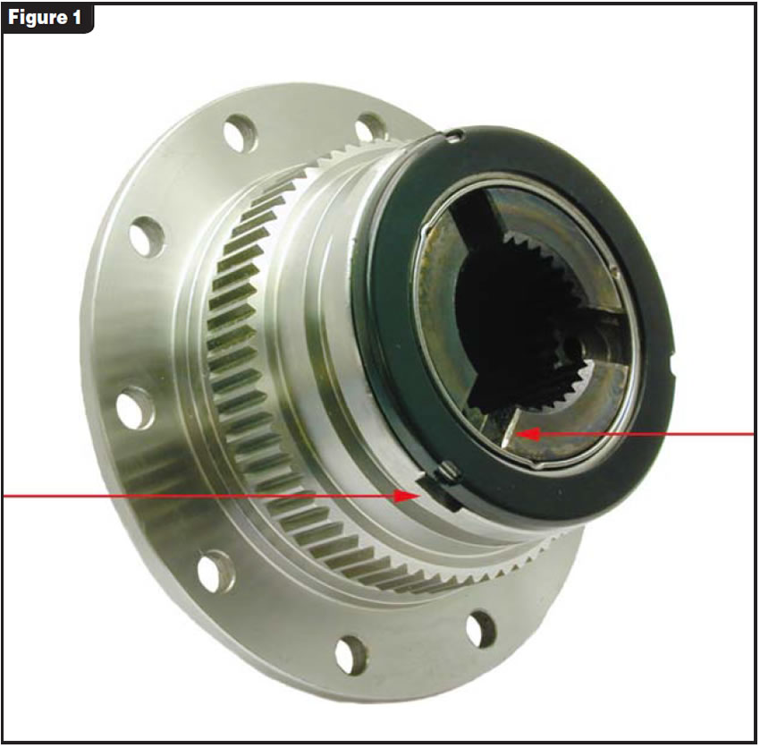
Some shops had concerns about contact between the turbine hub and cover. Early attempts to put a bearing or thrust washer onto the front of an E4OD turbine hub did prevent metal-to-metal contact between the hub and cover. These also may have created flow issues that caused some clutch failures and/or restricted lube oil to the transmission and possible lube-related failures. The flow issue was soon resolved: The E4OD turbine hubs that are used with bearings or thrust washers all have lube passages for this reason (see Figure 1).
The 4R100 has come by its flow problems honestly. It has inherited them from the E4OD.
Figure 2 shows a typical 4R100 converter with a multi-plate clutch. The converter-charge/clutch-release oil passes between the stator support and the turbine shaft. At the front stator bushing it must pass through the cavities that direct the oil around the bushing. It then exits through the three slots between the turbine shaft and the turbine hub. On an E4OD converter there is an unrestricted flow between the clutch and cover that not only keeps the clutch from dragging but also continues on to the transmission lube circuit. This is accomplished by the oil passing between the turbine hub and the cover when there is no bearing and by passing through the milled slots in the turbine hub when there is a bearing on the hub.
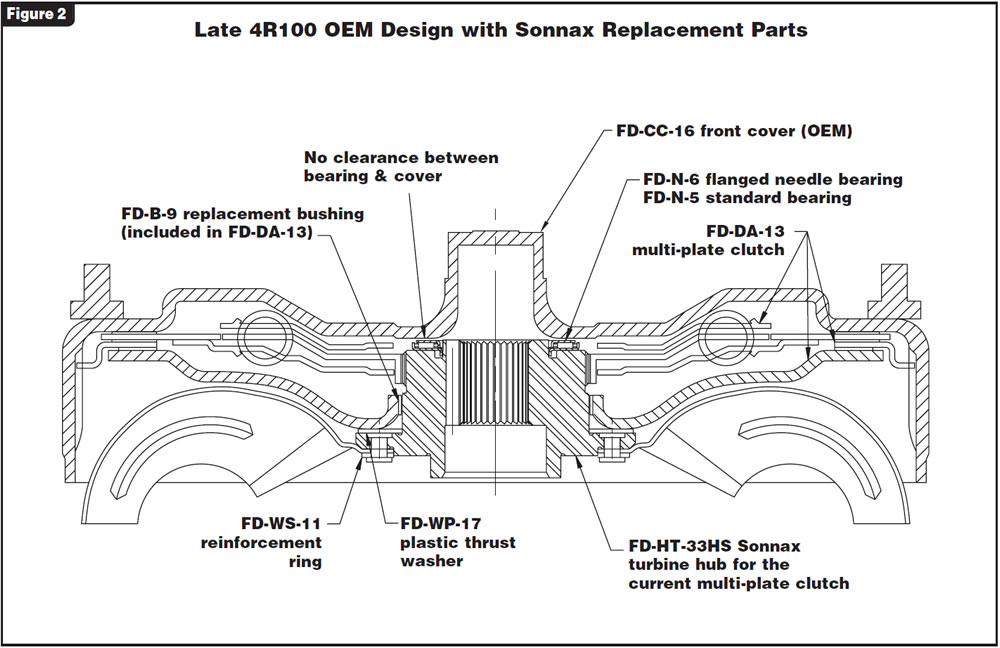
The 4R100 turbine hub with the bearing has no lube passages that bypass the bearing. The three slots on the ID allow the oil to pass only between the turbine shaft and the hub. Referring to Figure 2, you can see how the bearing restricts the flow. Converter-charge/clutch-release oil must either be forced through the bearing or squeezed between the bearing and cover. For this reason, converter endplay is critical in a 4R100. A minimum of 0.035 inch to 0.040 inch is needed to allow sufficient clutch-release oil to keep the clutch from dragging on the cover. You also must remember that the greater the endplay, the more likely it is that you will create an impact-related bearing failure. There is a fine line between endplay clearance that is friendly to both the clutch and the bearing and clearance that is not. Too much endplay affects bearing life, and too little endplay affects clutch life.
Some converter shops have made modifications to improve flow. Milling slots across and below the bearing-support surface like those on the E4OD shown in Figure 1 is one way for the oil to bypass the bearing. Another way is to mill slots in the cover (not shown) to accomplish the same thing. Either of these methods will work, but you must take care to ensure proper support for the bearing. You don’t want to cause a bearing failure by improving the flow. One enterprising shop even stole a page from the 5R110W playbook. They drilled three diagonal holes in the 4R100 turbine hub to allow the oil to bypass the bearing (see Figure 3).

As with other lockup converters, the time it takes to exhaust the oil from in front of the clutch for lockup apply has an effect on clutch-apply feel. When the flow of exhausting oil is restricted, the clutch apply is slower and the feel will be softer. Clutch-apply oil enters the converter through the rear stator cap, and a restriction at the cap also can affect lockup feel. Normally, the in-and-out flow of oil is metered very well in the non-lockup mode. The front stator-support bushing meters the converter-charge/clutch-release oil entering the converter, and the rear stator cap meters the oil leaving the converter. With proper end clearance they do a good job of balancing converter charge.

Ed Lee is a Sonnax technical specialist who focuses on issues of interest to torque-converter builders. ©2006 Sonnax Industries Inc.