
TASC Force Tips
- Author: Ed Lee
No OD When Cold, In & Out of OD When Hot
A 1994 Dodge R2500 pickup was brought to a transmission shop. The customer complaint was no overdrive when cold and that as the vehicle got up to operating temperature the overdrive would engage but would go in and out with throttle opening.
The vehicle was used primarily to tow a horse trailer. It had 200,000 miles on the odometer, but most were highway miles. A complete overhaul had been done at another transmission shop about six months earlier, at about 180,000 miles. About a month earlier the vehicle had been taken to a second transmission shop with the same complaint, and the transmission temperature sensor was replaced.
A thorough inspection of the vehicle was performed. No transmission-related codes were present when the scan check was performed, and no history codes were found. The road test did verify the condition, and the technician performing the road test commented that the vehicle drove as if it had a bad throttle-position sensor (TPS) or a TPS that was out of adjustment. A check of the data stream showed that the TPS did read zero at idle and had a full, smooth range to 100%. Checking the TPS in this manner proved to be a mistake – the same mistake made by the first two shops that worked on the vehicle.
The TPS angle, as read on the data stream, will always start at zero and, as long as it is functioning properly, will advance with throttle opening. On this vehicle the TPS was reading 100% by the time the throttle was halfway open. The correct way to check the TPS on this vehicle is to attach the positive lead of a volt meter to the center wire of the TPS and attach the meter’s negative lead to a good vehicle ground. The volt meter should read 1.0 volt (±.2 volt) at idle and 3.5 volts (±.4 volt) at wide-open throttle. On this vehicle the volt meter read more than 1.0 volt at idle and max TPS voltage at full throttle. The 3.5 volts that should have been the wide-open-throttle reading was reached at about half-throttle.
At this point you would think that the TPS was defective, and many good throttle-position sensors have been replaced on the basis of this reasoning. The actual root cause of the problem was a throttle-linkage rod that was out of adjustment. The throttle-linkage rods have always had a problem with corrosion at the joints of all 5.9-liter Cummins turbo-diesel engines. In July 2002 DaimlerChrysler Inc. issued safety recall #B15 for diesel-engine throttle linkage. Unfortunately for the consumer, the recall was assembly-plant, date and VIN specific. The earliest covered vehicle was manufactured at the St. Louis north assembly plant on July 22, 1996 (VIN MDH0805XX). The recall ended at all three assembly plants on Dec. 31, 1997 (with VIN 1231XX).
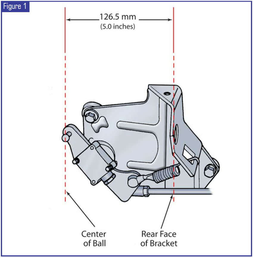
Since the customer’s vehicle did not fall within the parameters of the recall, the corroded linkage rod was replaced at an independent garage. The independent garage was not aware of how critical the linkage-rod adjustment was. The instructions that accompany the B15 safety recall are 11 pages long. The importance of the throttle-linkage-rod adjustment is a major concern. When the rod is adjusted properly, the distance between the center of the ball on the throttle lever and the back of the throttle-cable mounting bracket will be 5 inches or 126.5mm (see Figure 1). The ± variance on the adjustment is 1.0mm (that’s the thickness of a dime). This bold-face warning is part of the instructions: “Do not lengthen or shorten the linkage rod more than 1.0mm from the dimension 126.5mm (5.0 inches). If voltage requirements cannot be met by linkage adjustments (125.6 to 127.6mm), replace the TPS.”
When the throttle-linkage rod is adjusted properly, as the accelerator pedal is depressed halfway to the floor the throttle lever and the linkage rod connecting the throttle lever and the injection-pump lever both should move. As the accelerator pedal is depressed past this point, the movement of the linkage rod should stop and the throttle lever will continue to move toward the rear of the vehicle. This visual check does require two people to perform but may be worth the time spent in the long run.
Special thanks to Matt Hetrick and David Carothers of Deltrans Inc. for their technical assistance in writing this article.

Ed Lee is a Sonnax Technical Specialist and a member of the TASC Force™ (Technical Automotive Specialties Committee), a group of recognized industry technical specialists, transmission rebuilders and Sonnax Industries Inc. technicians. ©2005 Sonnax


